Prototype 6

Bill of materials
Non-Electronics
- Approx. 40cm x 30cm non-conductive fabric, e.g. modal jersey
- 3x5cm Velcro to attach the PCB to the fabric
- 9x snap buttons (e.g. Prym 390107)
- or any other snap buttons made from conductive metal, and not treated with an isolating outside layer
- 20cm Shrink-on tube, about 4mm->2mm.
- When shrunk, it should fit tightly onto the insulated wire of the jumper cable
Electronics
See also Circuit 9.1
- 1x Arduino Nano 33 BLE Sense
- Along with the included two pin headers (1 row, 15 pins, 2.54cm distance, straight)
- 1x
- 1x AAA Battery, preferably rechargeable
- 1x Pin header, 1 row, 17 pins, 2.54cm pin distance, angled (output pins)
- 1x Three-pin slide switch, 2.54cm pin distance (power switch), small enough to fit on the PCB
- 2x Keystone 82 (AAA battery clips)
- 1x Inductance coil (L1), 1206 Package, 4,7µF, rated for ≥280mA
- 2x Capacitor (C2, C3), 1206 Package, 10µF or more, rated for ≥6V
- 1x Resistor (R1), 0805 Package, 1MΩ/1%
- 3x Resistor (R2-R4), 0805 Package, 110kΩ/1%
- R3 and R4 can probably be anything from 47kΩ to 1MΩ but their values must be identical
- 1x TPS61220DCK (U1) Step-up voltage converter, SC-70 Package
- The chip should be rotated so that the line on the chip is on the same side as the longer one of the two lines on the U1 footprint on the PCB.
- 1x LM321 (U2) Operational amplifier
- 9x 20cm jumper cable, one side needs to be female, the other side doesn't matter
Optional
- 1x Pin header, 1 row, 3 pins, 2.54cm pin distance, angled (jumper pins)
- 2x Pin header socket, 1 row, 15 pins, 2.54cm pin distance (if you want to be able to remove the arduino easily)
- 9x Capacitor (C1, C4-C11), 1206 Package, as much F as you want. These are optional but recommended, as they should theoretically improve the signal quality.
- Some 2.54cm-distanced pin jumpers
Tools
- Soldering iron with a fine tip for SMD parts
- Soldering tin, lead-free
- Worked great for me: Sn95.5 Ag3.8 Cu0.7, 0.35mm⌀
- Soldering flux (or some margarine...)
- Tweezers for SMD parts
- Sewing machine with any stretch stich
- Needle & thread to sew velcro onto the PCB
- Scissors for fabric
- Knife for cutting solder jumper
- Lighter for shrink-on tubes
- Hammer or whatever tool you need to assemble the snap buttons
Assembly
Electronics
- Cut the "3.3V" solder jumper on the Arduino to enable it being powered by a battery
- Solder on both of the straight 15-pin headers to the Arduino
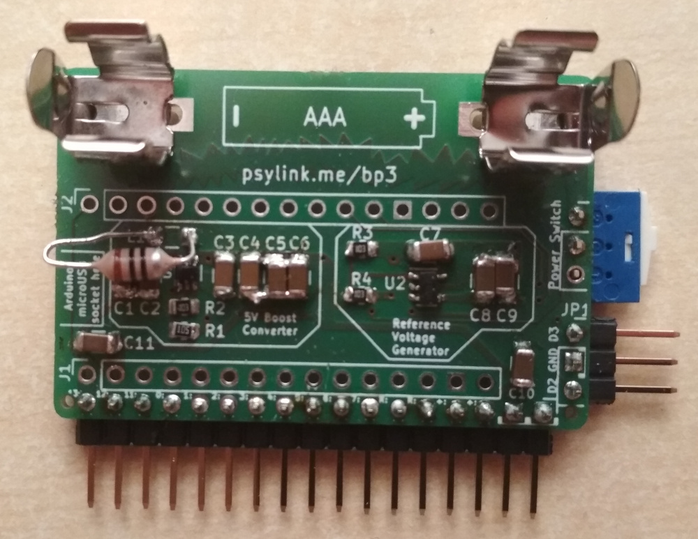
- Solder on all the parts of the PCB
- Attach battery clips (doesn't need to be soldered) and battery
- If you use the pin sockets, you can just plug in the Arduino now. See the "Arduino micruUSB socket here" inscription for how to rotate the Arduino.
- Otherwise, do a test run and check
- Whether the circuit produces 5V on V+ and 2.5V on Vref,
- Whether it can power the Arduino (connect GND, and V+ to Arduino's "3.3V" pin) and still produce 5V and 2.5V
- Ideally, run GNURadio or PsyLink UI to establish a bluetooth connection to see if it's working
- Once all tests work, solder on the Arduino. Again, see the "Arduino micruUSB socket here" inscription for how to rotate the Arduino.
- Otherwise, do a test run and check
- Attach Velcro to the PCB on the mounting holes on the corners (you may need to remove battery clips to reach the holes) with needle and threat
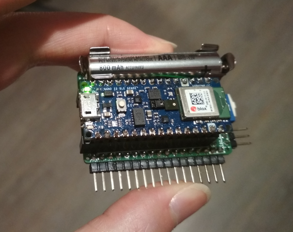
In the end, it should look like this:
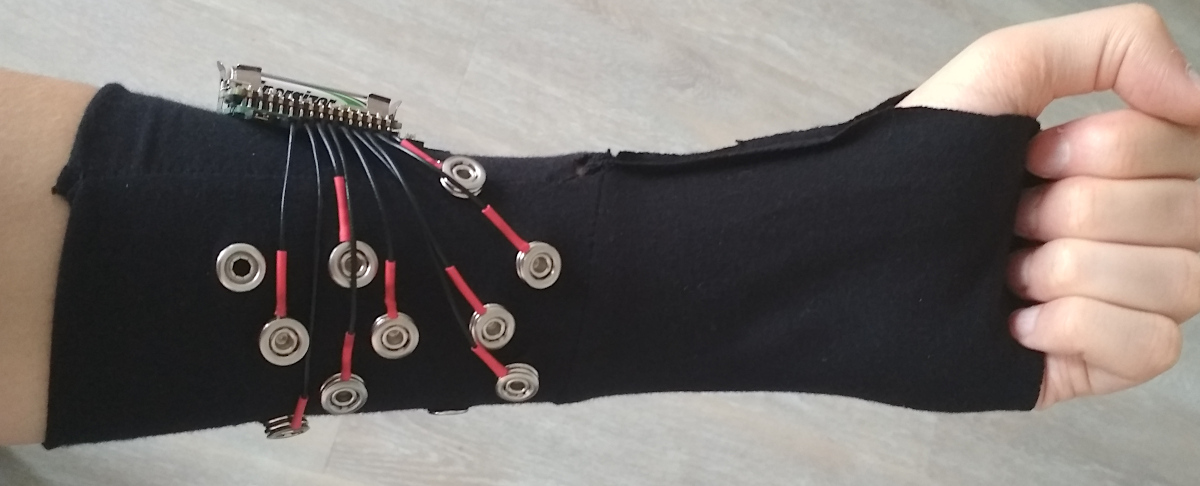
Fabric
- At minimum, sew a 10cm long cylinder that fits tightly around the middle of your forearm
- Add whatever features you like, e.g.:
- wrappable cover for the electronics
- velcro straps to tighten it to various arm widths
Electrodes
- Attach the female snap button to the fabric
- One of them (the ground electrode) should ideally be placed at the Ulna or Radius bone and should stay on the bone (if possible) as you twist the wrist
- The others can go whereever you want. You may need to test nice spots that work with your body. I recommend the area around the Flexor Digitorus Superficialis in the middle of your forearm, since most other muscles provide signals that are redundant to the IMU signals (gyroscope/accelerometer)
- Hammer together the two parts of the male snap button, but not completely, leaving a little space for some wire
- Attach Cable
- Take one jumper cable (female-to-any)
- Only the female end is used
- Cut off the other end at desired length
- Remove 4-5cm of insulation at the cut end
- Add 1.5cm of shrink-on tube onto the wire (don't burn yet)
- Wrap the exposed wire around the ridge between the two parts of the male snap button
- Twist the male snap button to tighten the wire (don't overdo it, we don't want it to break)
- Hammer the male snap button tight
- Pull the shrink-on tube towards the electrode and burn it
- Repeat this 9 times. Each cable should be just long enough to reach the target electrode on the fabric.
- Plug the ground electrode into one of the Vref pins of the board, and the other electrodes into the A0-A7 pins
If you require more detailed assembly instructions or further information, please contact the author.
- See blog post Running on AAA battery
- Bill of materials: bom_p6.ods
- Components:
- Date: 2021-06-21