PsyLink is experimental hardware for reading muscle signals and using them to e.g. control the computer, recognize gestures, play video games, or simulate a keyboard. PsyLink is open source, sEMG-based, neural-network-powered, and can be obtained here.
This blog details the steps of building it and shows recent developments. Subscribe to new posts with any RSS reader, and join the community on the Matrix chatroom.
- All posts on one page
-
2025-05-01: PsyLink Talk
-
2024-08-16: Mass Production #2
-
2024-08-01: Android: First Step
-
2024-07-25: Rev2 Firmware
-
2024-07-24: Prototype Fund
-
2023-08-25: Data Sheets
-
2023-05-31: Prototype 10
-
2023-03-22: Enhanced Signal by >1000%
-
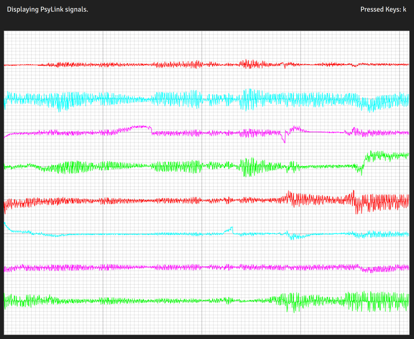
2023-03-06: Sample Signals
-
2023-02-05: 2022 Retrospective
-
2022-02-24: Added Bills of Materials
-
2022-02-23: 3M Red Dot electrodes
-
2022-02-22: Microchip 6N11-100
-
2022-02-16: Next Steps & Resources
-
2022-02-15: Mass production
-
2022-01-19: Prototype 9 + Matrix Chatroom
-
2022-01-18: HackChat & Hackaday Article
-
2021-12-19: Prototype 8 Demo Video
-
2021-12-18: Prototype 8
-
2021-12-16: INA155 Instrumentation …
-
2021-12-15: Power Module 4
-
2021-11-30: Batch Update
-
2021-07-17: Neurofeedback: Training in …
-
2021-07-06: New Frontpage + Logo
-
2021-06-24: Cyber Wristband of Telepathy …
-
2021-06-21: Running on AAA battery
-
2021-06-16: Power Module 3
-
2021-06-10: Believe The Datasheet
-
2021-06-04: Back to the Roots
-
2021-05-31: Website is Ready
-
2021-05-29: Dedicated Website
-
2021-05-17: Gyroscope + Accelerometer
-
2021-05-14: Wireless Prototype
-
2021-05-09: Power Supply Module
-
2021-05-07: New Name
-
2021-05-06: Finished new UI
-
2021-05-04: Higher Bandwidth, new UI
-
2021-04-30: PCB Time
-
2021-04-29: Soldering the Processing Units
-
2021-04-28: Going Wireless
-
2021-04-24: First Amplifier Circuit
-
2021-04-19: Amplifiers
-
2021-04-15: Multiplexers
-
2021-04-14: Data Cleaning
-
2021-04-13: Cyber Gauntlet +1
-
2021-04-11: Adding some AI
-
2021-04-09: F-Zero
-
2021-04-08: Baby Steps
-
2021-04-03: The Idea
PsyLink Talk
└2025-05-01, by RomanHey folks, I held a talk on PsyLink at Chaos Computer Club Cologne and it's been recently uploaded:

Here are the links to the recording of the talk and the slides.
It gives a comprehensive overview on
- why I created PsyLink
- the architecture of the hardware and software
- the biological, technical, and philosophical background
- the future plans, goals, and problems
and ends with a little demo of using PsyLink, incl. collecting training data, live-training of a neural network, and using gesture recognition to input key presses on my laptop.
If you're interested in this project, this is definitely the best starting point right now. :)
Mass Production #2
└2024-08-16, by RomanRecently I've been assembling some PsyLinks for anyone who is curious to try it out:
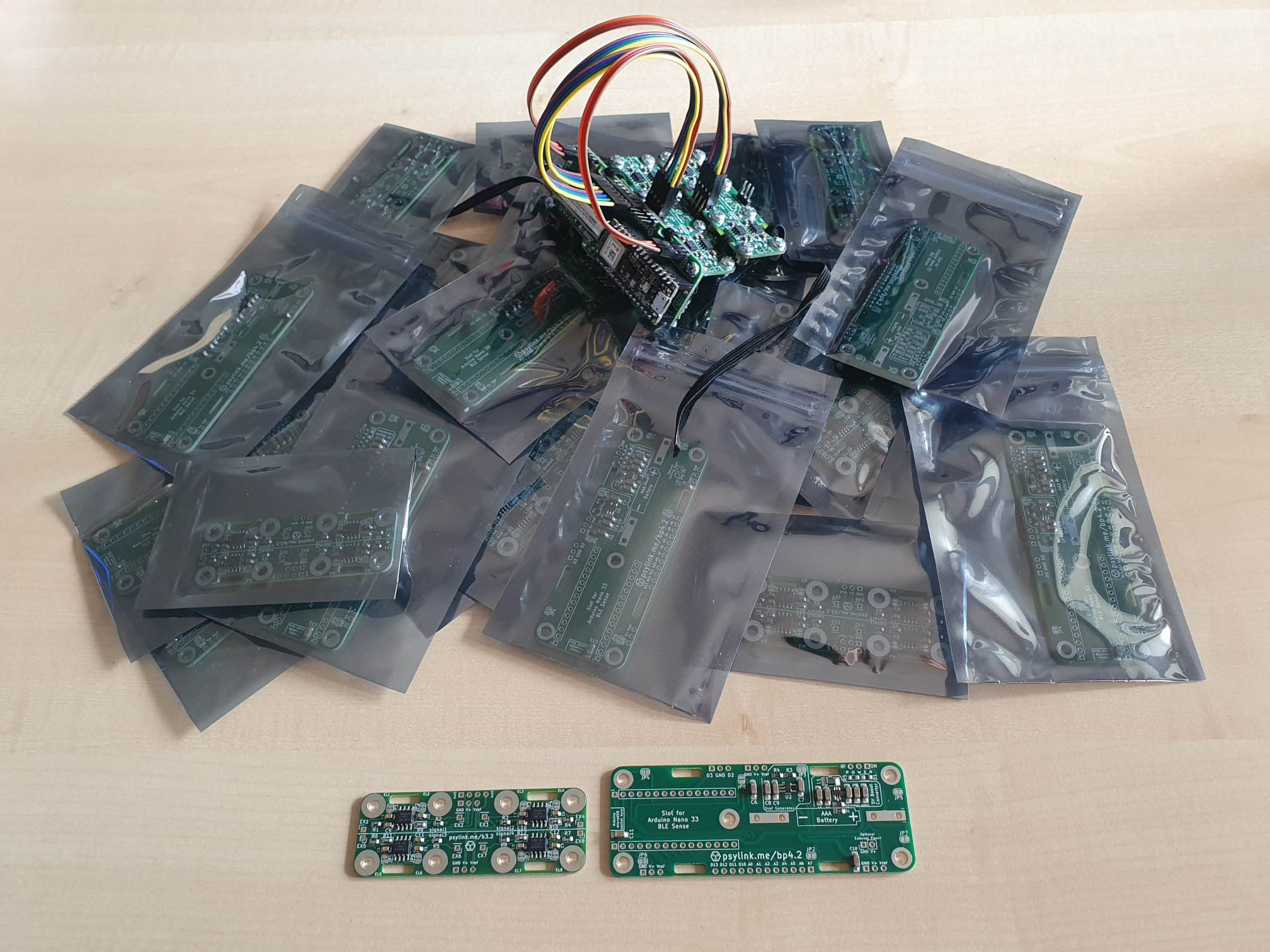
It was a huge help that the SMD parts were already soldered on by PCBWay. These were partially sponsored by PCBWay, which I am very grateful for. The quality is perfect, couldn't have done it better myself.
You can't imagine how happy I am for not having to hand-solder the tiny SC-70 voltage booster (2mm x 2mm) anymore! I also appreciate that PCBWay left no break-off points on the sides of the PCBs, since they tend to scratch the skin and I usually have to file them off manually.
I still can't outsource the assembly of through-hole components since I manually have to cut the connectors short enough so the bottom side doesn't scratch the skin. But I hope some day I can fully outsource the assembly and can focus on research and development instead.

Of the 9 PsyLinks on the photo, 4 are already reserved, but feel free to ask for one if you are interested!
Android: First Step
└2024-08-01, by RomanThe new PsyLink GUI now builds on Android!
One part is still missing: Bluetooth connections. So, currently the app is effectively useless, as it will scan for PsyLink devices but never find any. A good first step though.
You can find the Android build instructions in the BUILDING.md. It's quite the wrestling match.

Rev2 Firmware
└2024-07-25, by RomanThe PsyLink Arduino firmware now officially supports revision 2 ("Rev2") of the Arduino Nano 33 BLE (Sense).
You can toggle between Rev1 and Rev2 by setting the variable ARDUINO_REV2 to true or false.
Prototype Fund
└2024-07-24, by RomanI almost can't believe it, but this project is receiving a grant from the Prototype Fund!
The funding goal is to build new software for the PsyLink that runs platform-independent and user-friendly, as one of the major issues with PsyLink so far is how hard it is to set up the software. The current software uses Python and is Linux-only, and users have either written their own front end software or gave up trying to use it entirely. I plan to fix this with a Rust reimplementation that will run on Linux, Windows and Android.
This is what the new software looks like so far:
In contrast to the previous software, this is just a double-click on a single binary file, with no dependencies and no necessary user interaction - it automatically finds the PsyLink over bluetooth and connects to it.
The plan is to finish this in September and give a demo in Berlin.
Prototype Fund is looking for more applicants every 6 months, and I can wholeheartedly recommend them. The people are wonderful and it's been a great experience so far. Give it a try too, if you're based in Germany and your project fits the requirements. For reference, here is my own application:
My own Prototype Fund application (in German) can be found here as a reference.