Power Supply Module
I made an updated schematic (circuit 6) that shows more clearly how the modules are connected. Also corrected an error with the feedback of the voltage follower, and changed values of some resistors/capacitors:
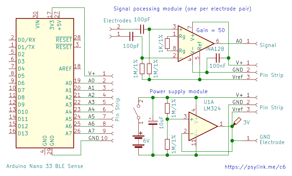
I also constructed the power supply module:

but for some reason it didn't work. All the parts seemed to have been connected the right way, I couldn't find a short circuit, but the output voltage was ~0.5V instead of ~5V, and the reference voltage was just 0. I blame a possibly broken opamp.
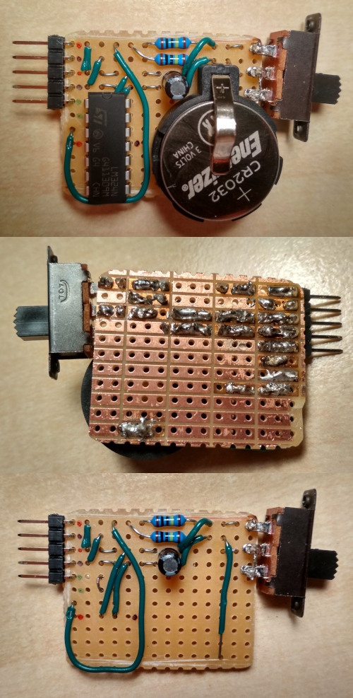
Well, I didn't like the design and length of the circuit board anyway, so it didn't hurt trashing the thing and building this beauty instead:
I'll use female-to-female jumper wires to connect V+ and GND to the arduino, and 3 more wires to bootstrap the power supply of the mesh network of the signal processing modules.
Notes:
- Yep, that's 2 coin cells in there
- Outputs: Black=Ground, Red=V+, Green=V+/2 (reference signal)
- There's an optional second green pin for the ground electrode
- If you're wondering why I'm using a big ass quad opamp when I just need a single output: I don't have a smaller one atm.
- I totally need to move this to a SMD PCB in the long run, this is still too bulky, but will do for now. It's about the dimensions of a 9V battery.
I wonder if some 深圳人 will read this, shake their head, and view me as a primate struggling to make fire with sticks. That's what it felt like to construct this thing anyway. Nevertheless, I'm one step closer to the next prototype :)
- Newer post: Wireless Prototype
- Older post: New Name
- All posts on a single page
- Date: 2021-05-09
- Author: Roman