Wireless Prototype
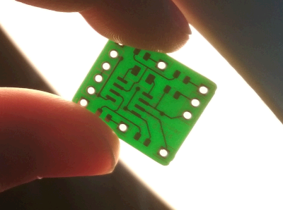
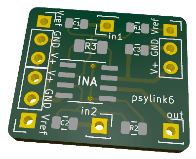
Hell yeah! The PCBs arrived:
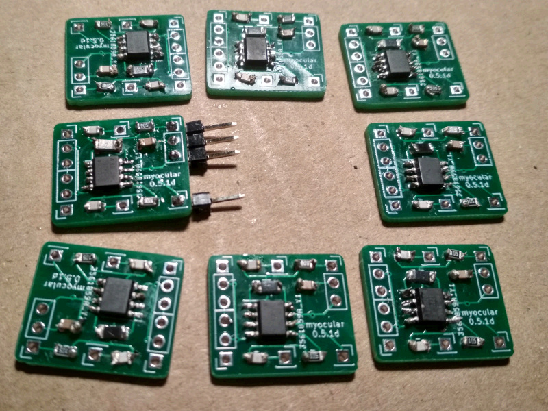
Soldering & Sewing
I never soldered such tiny SMD parts before, and didn't have proper tools, way too thick soldering tin and solder iron tip. I was also too impatient to order some, so after hours of torture, I produced this batch:
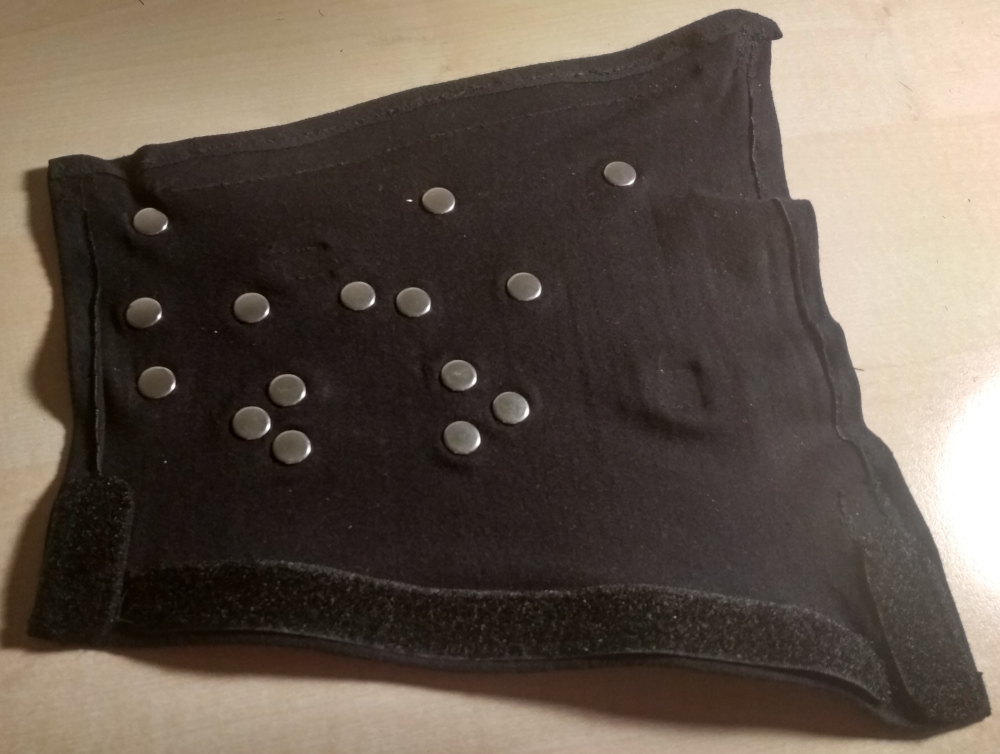
The new prototype was to be a forearm sleeve of modal fabric once again, with snap buttons for electrodes which will also hold the signal processing PCBs in place.
But how to attach the Arduino and the power supply module to the sleeve? I thought, "why not Velcro?" (hook-and-loop fastener) and started sewing it to the circuit boards:
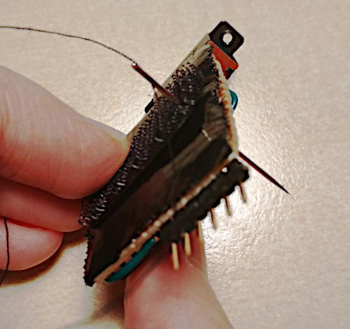
(Yes, doing it felt as weird as it looks)
So I sewed the sleeve, assembled one electrode pair along with its processing PCB, and wired everything together. Here's me being overly excited about the first wireless test run:
Electrode Placement
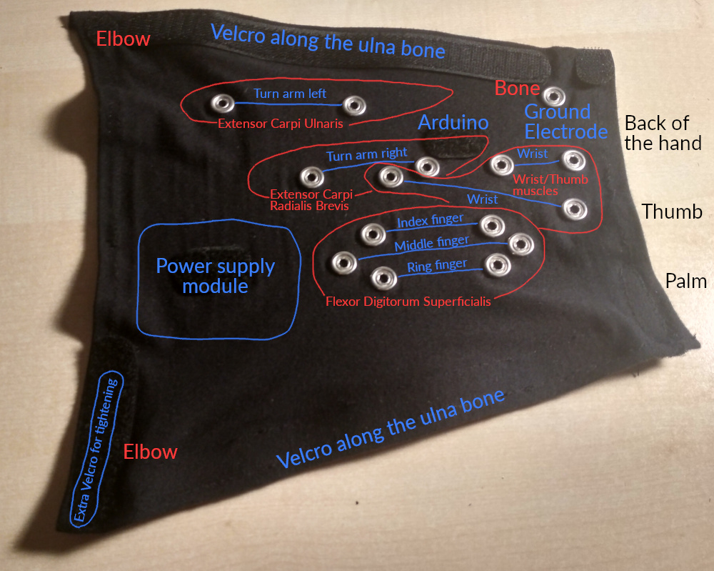
Then there was the question of where to put the electrodes. Using an improvised muscle map along with two flexible electrodes on individual straps, I could find spots whose electrical activity correlated with turning the arm, twisting the wrist, or pressing individual fingers onto the table:
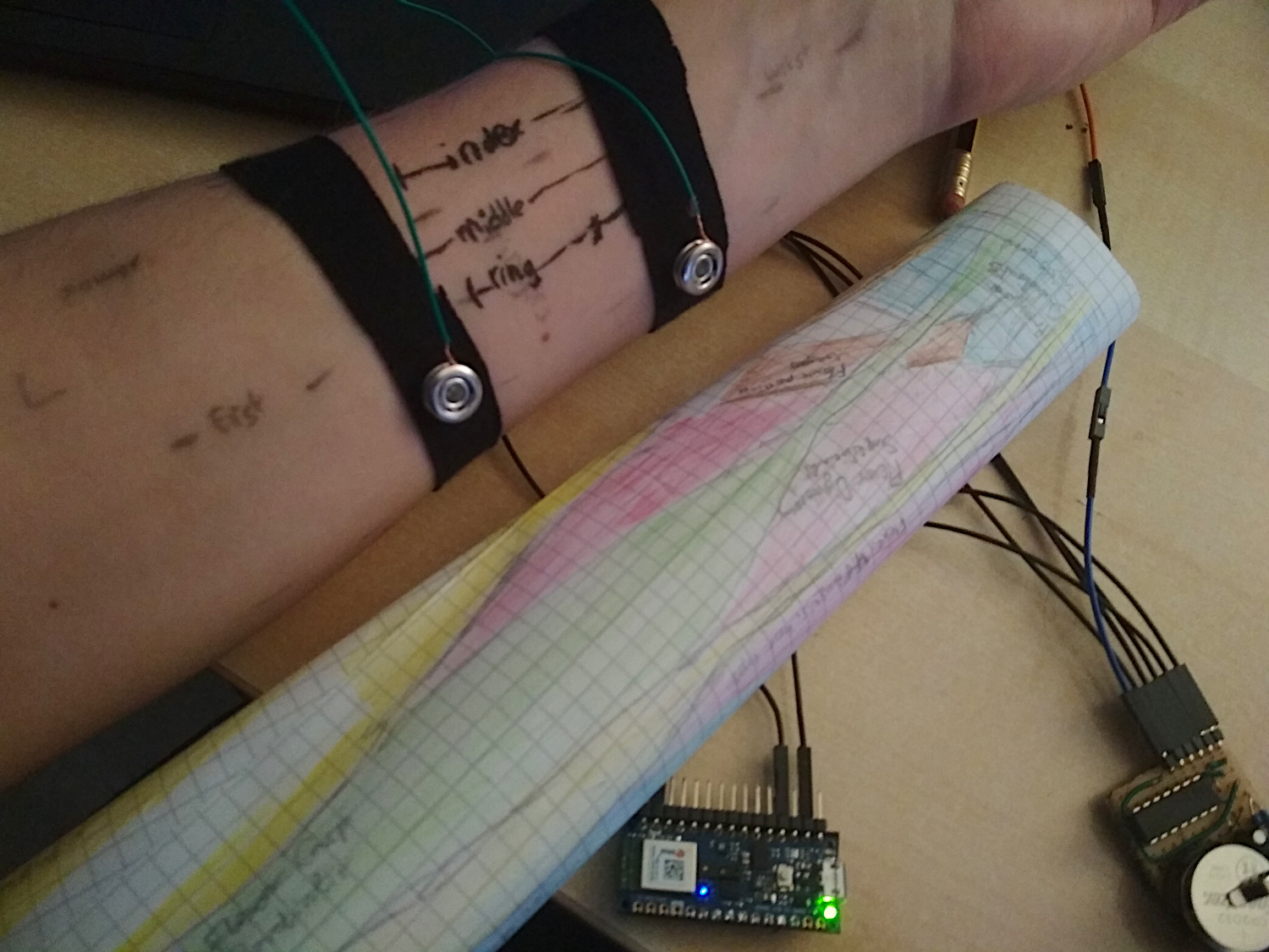
Flexor Digitorum Superficialis was particularly interesting; I found 3 areas over that muscle which map to the index, middle and ring finger each. For turning the arm and wrist, the muscles with "Carpi" in their name (e.g. Extensor carpi ulnaris) worked pretty good.) A huge disappointment was Extensor Digitorum, which is supposed to be active when fingers move up, but I could not find such correlation. Then again, I use snap buttons for electrodes, so I'm not that surprised.
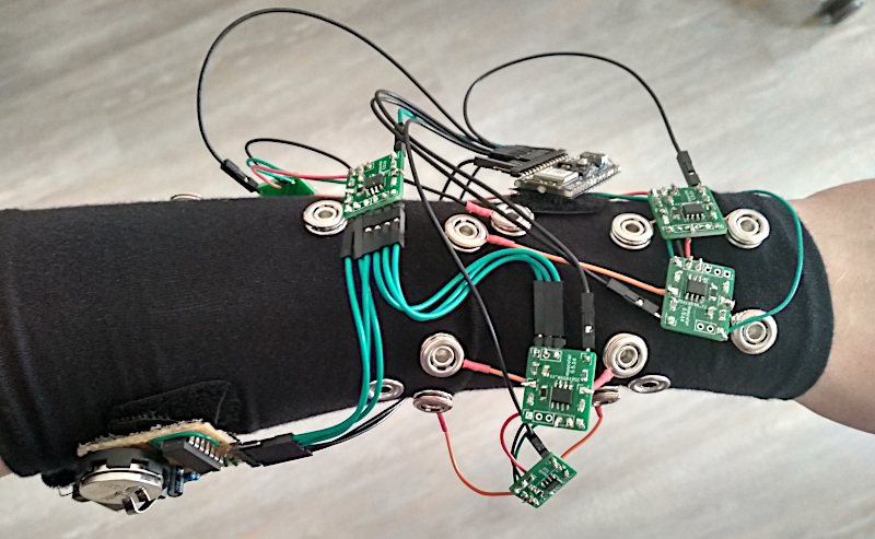
The final layout of the electrodes:
This piece is fully separable from the electronics and therefore machine washable.
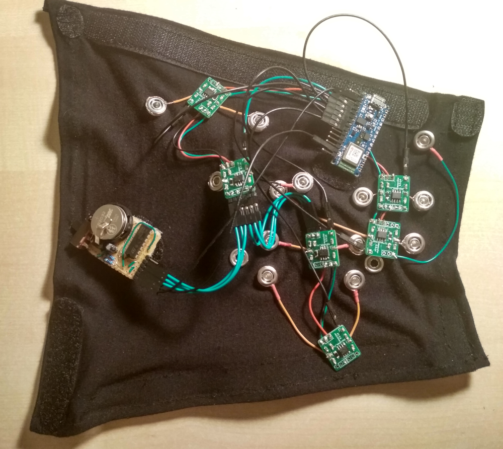
Here are additional pictures of the inner side, the separated electronics, as well as everything combined. This nicely shows the tree topology of the green signal processing modules that pass through the power supply among each other to reduce the volume of wiring.
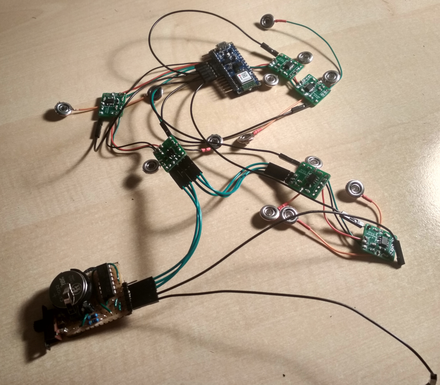
I could have had 8 electrode pairs, but only added electrodes for 7. On these pictures, the electrode pair for the middle finger is also missing the circuitry. That's mostly a testament to my laziness.
Actually I regret where I placed the Arduino, since there would be some great spots for electrodes, but I noticed that too late. Will try to remove the Velcro and maybe add an 8th electrode pair there.
The final cyb3rware:
While the signal was quite strong with the test straps, I found that the amplitude of the signal went way down once I had everything attached to the sleeve. Maybe there was some kind of interference from the Arduino or the power supply being closer to my skin, or maybe the modal fabric messes with the signal somehow. I hope I can compensate for this by increasing the signal amplification multiplier, but I leave that for later.
This issue occurred with a single electrode pair already, but was aggravated when attaching more of them. It might help if I add some flux capacitors to the power supplies to prevent cross-interference.
Test Drive
I drove F-Zero with Prototype #2 before, but back then I cheated a little bit. It only recognized 2 keys, left and right, and I accelerated with the keyboard using my other hand.
This time I hoped I could do better, and trained the AI to recognize 3 different keys (left, right, accelerate) from my muscle signals. It even kinda worked!
This was after recording ~2000 muscle signal samples over 1-2 minutes and training a convolutional neural network for 25-50 epochs (<1 minute) on the data using the PsyLink UI. I used 4 electrode pairs, all of which are on the dorsal side of the forearm.
Analysis
In the racing game, I didn't make it to the finish line yet, and it does look pretty clumsy, but I blame it on the software still having some obvious flaws. It doesn't even account for packet loss or packet duplication when handling the Bluetooth packets yet. Hope it will go better once I fixed them. Also, the test drive was with only 4 electrode pairs.
The raw values as visualized with the GNURadio flowgraph while randomly moving my forearm/wrist/hand show that the correlations between the signals are low enough to be theoretically useful:

If you enlarge this image, you'll see that especially the black line is considerably different, which I suppose is because it's the only electrode pair that spans across several muscles. And that makes me wonder: Am I doing too much pre-processing in hardware before I feed the data into the AI? Sure, the differential amplification of this new prototype enhances small signals that the previous prototypes might have not detected, but a lot of information is lost too, like the voltage differences between electrodes from different electrode pairs.
Maybe I can compensate for this by simply adding some more electrode pairs that span muscles. I'm also thinking of switching to a design with 32-64 randomly placed electrodes -> buffer amplifiers -> multiplexers -> analog to digital converters of the Arduino. That way, the neural network can decide for itself which voltage differences it wants to look at.
New PCB layout
While soldering the PCB, I found some flaws and made these changes to the previous PCB:
- Added silkscreen labels to the connectors and components. I was sure I wouldn't mix up anything since there aren't many connectors, they're nicely symmetrical, and I'm the designer after all. But nope. I still mixed them up.
- Removed unnecessary vias. (I was actually not sure whether the pin holes will really conduct between the front and the back side of the board, so I added vias as a safety measure.)
- The label now shows the new name "psylink" instead of "myocular"
- A friend also gave me the tip to increase the thickness of power supply wires
- Newer post: Gyroscope + Accelerometer
- Older post: Power Supply Module
- All posts on a single page
- Date: 2021-05-14
- Author: Roman