Development Log
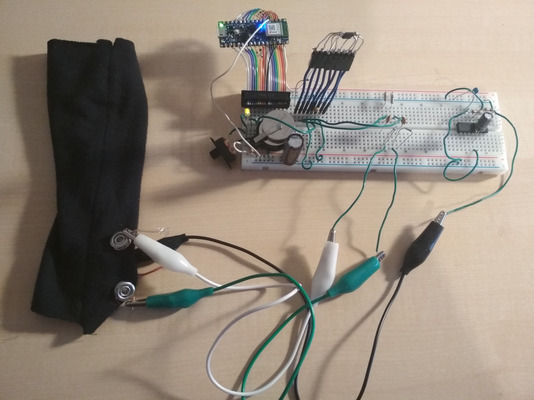
PsyLink is experimental hardware for reading muscle signals and using them to e.g. control the computer, recognize gestures, play video games, or simulate a keyboard. PsyLink is open source, sEMG-based, neural-network-powered, and can be obtained here.
This blog details the steps of building it and shows recent developments. Subscribe to new posts with any RSS reader, and join the community on the Matrix chatroom.
Intro
We don't have to drill a hole into skull to get access to your nerve signals.
Muscles naturally amplify them, allowing us to easily read them through skin,
and use them for useful things like controlling a computer or an artificial
limb.
This is not science fiction, check out what's out there already:
You could argue that we use our nerves/muscles to control keyboards already
(and pretty much anything else). And for the time being, there are clearly
superior human input devices. But there are reasons to do this:
- Bandwidth: Keyboards are limited to ~120wpm (~84 bit/s). Hopefully we can squeeze out some more by sapping the nerves directly.
- Hands: Not everybody has them. You also may not want to use them, e.g. due to injury, or because they're occupied with other tasks.
- Cyberpunk: The books predicted there will be neural interfaces in the future, therefore we must create them.
This page documents my process of building one. Note that I'm no expert and I
neither have a plan, nor do I know what I'm doing. I just thought, how hard
can it be? If the architect of the Internet Exploder can build
one,
surely I can do it to.
The Idea
└2021-04-03, by Roman
On this day, I got the idea and started researching EMG design and signal
processing, motor neurology basics, as well as existing projects.
Soon I realized that I will need a microcontroller to record and process the
signals. I considered the Raspberry Pi Pico and Arduino Nano 33 BLE Sense, and chose the Arduino because:
- Bluetooth
- More analog-to-digital converter inputs
- TensorFlow Lite support, which would allow me to leverage neural networks for signal processing. This is a bit of a stretch, can't wait to get disappointed by this :)
I wish there was a decent battery/UPS shield, couldn't find one so far.
Baby Steps
└2021-04-08, by Roman
The Arduino arrived. I have no electrodes though. But what are electrodes,
just some pieces of metal taped to your skin, right? Let's improvise that:

There are two pieces of aluminum foil taped to my skin, held together with blue
medical wrap.
The educational material about electromyographs that I've seen described a
chain of hardware elements to process and clean up the signal:
- amplification
- filtering
- rectification
- antialiasing
- smoothing
- averaging
- etc.
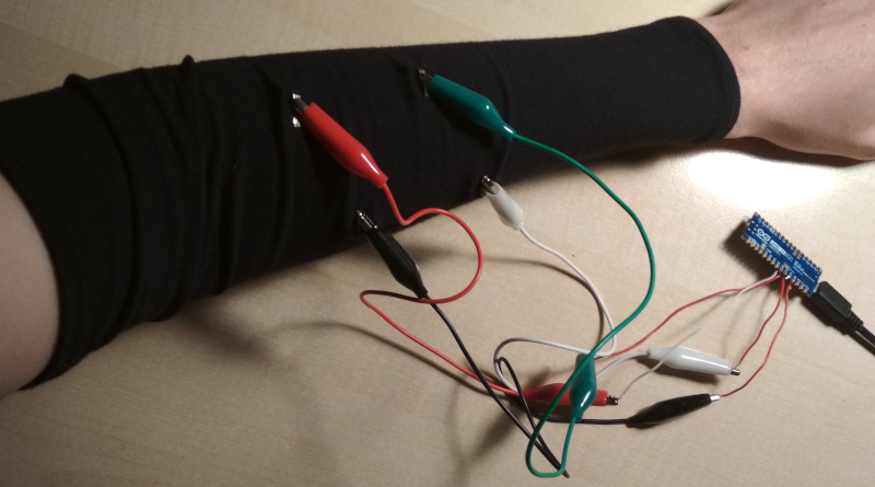
But I thought, let's focus on the MVP. Why not simply hook the electrodes
straight to the analog input pins of the Arduino with some alligator clamps?
Worked fine. I did minimal signal processing in software though, you
can find the source code here.
This video shows the myoelectric signal on Arduino IDE's built-in signal
plotter:
F-Zero
└2021-04-09, by Roman
The look of the first device was way too unprofessional, so I pulled out my
sewing machine and made a custom tailored sleeve from comfortable modal fabric.
On the inside, I attached some recycled studs that served as electrodes. Who
needs that expensive stuff they sell as electrodes when a piece of iron
suffices?
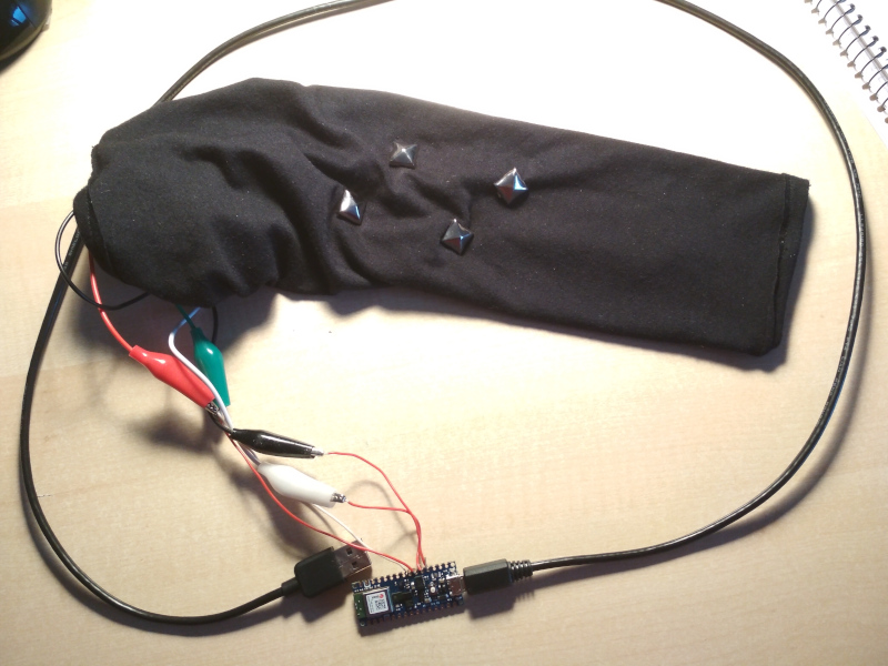
This time it had 4 electrodes. I targeted the middle and the distal end of two
muscles, the Brachioradialis
and the Extensor carpi radialis
longus.
I picked those muscles at random, because I honestly don't know what the fuck I
am doing.
Software-wise, I played around with moving average
and got reasonable signals, but it was clear that there was too much noise.
How to filter, though? I'm not going to solder some bandpass filter, that's
too slow and inflexible. There are simple algorithms for doing it in software
(link 1,
link 2),
but something seemed off about this method. In the end, I decided to learn how
to do a Fourier transform on the Arduino.
With this code
(inspired by this post),
I took 64 samples at a sampling rate of 1kHz, performed the Fourier transform,
cut out anything under 30% and over 50% of my frequency range, and then summed
up the amplitudes of the remaining frequencies to generate the output.
Still very crude, but it allowed me to get distinctive signal patterns for
various positions of my arm:
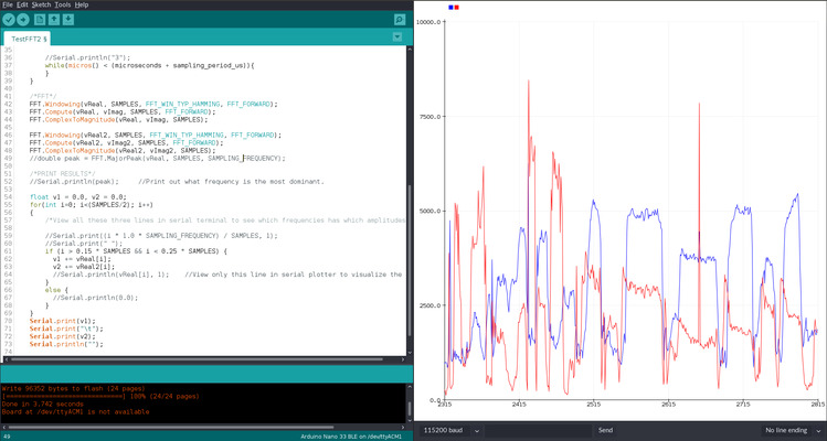
I was genuinely surprised that I got information of this fidelity and
usefulness from just hooking up 4 ADC's to semi random places of my forearm and
a software bandpass filter. This was good enough to use it as a basic input
device!
I wondered, can I control a racing car game with this?
To test that, I built this program
to read out the signals and convert certain ranges of values to keyboard
presses of the keys Left and Right. The value ranges need to be
calibrated before each use: I held my left arm like I'm grabbing an invisible
steering wheel, moved it left and right, and looked hard at the signal values
to find correlations like "signal A is always below X if and only if I steer
left". Once the calibration is done, the invisible steering wheel turned into
a magical keyboard with 2 keys =D
Right away I tried it out to steer in my favorite racing game, F-Zero:
Note that in addition to the steering wheel, I used my other hand to
accelerate.
I loved it, but there is still a lot of work to be done. The calibration is a
pain, especially since it needs to be repeated if the electrodes move too much,
which happens a lot with this kind of sleeve. Also I want more electrodes,
better signal processing, and data transfer via Bluetooth so I can run it off a
battery.
Adding some AI
└2021-04-11, by Roman
Most neural interfaces I've seen so far require the human to train how to use
the machine. Learn unintuitive rules like "Contract muscle X to perform action
Y", and so on. But why can't we just stick a bunch of artificial neurons on top
the human's biological neural network, and make the computer train them for us?
While we're at it, why not replace the entire signal processing code by a bunch
of more artificial neurons? Surely a NN can figure out to do a bandpass filter
and moving averages, and hopefully come up with something more advanced than
that. The more I pretend that I know anything about signal processing, the
worse this thing is going to get, so let's just leave it to the AI overlords.
The Arduino Part
The Arduino Nano 33 BLE Sense
supports TensorFlow Lite,
so I was eager to move the neural network prediction code onto the
microcontroller, but that would slow down the development, so for now I just
did it all on my laptop.
The
Arduino code
now just passes through the value of the analog pins to the serial port.
Calibrating with a neural network
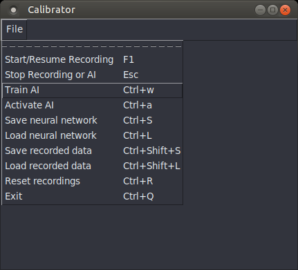
For this, I built a simple user interface, mostly an empty window with a menu
to select actions, and a key grabber.
(source code)
The idea is to correlate hand/arm movements with keys that should be pressed
when you perform those hand/arm movements. To train the AI to understand you,
perform the following calibration steps:
- Put on the device and jack it into your laptop
- Start the Calibrator
- Select the action "Start/Resume Recording" to start gathering training data
for the neural network
- Now for as long as you're comfortable (30 seconds worked for me), move your
hand around a bit. Hold it in various neutral positions, as well as
positions which should produce a certain action. Press the key on your
laptop whenever you intend your hand movement to produce that key press.
(e.g. wave to the left, and hold the left arrow key on the laptop at the
same time) The better you do this, the better the neural network will
understand wtf you want from it.
- Holding two keys at the same time is theoretically supported,
but I used TKinter
which has an unreliable key grabbing mechanism. Better stick to single
keys for now.
- Tip: The electric signals change when you hold a position for a couple
seconds. If you want the neural network to take this into account, hold
the positions for a while during recording.
- Press Esc to stop recording
- Save the recordings, if desired
- Select the action "Train AI", and watch the console output. It will train
it for 100 epochs by default. If you're not happy with the result yet, you
can repeat this step until you are.
- Save the AI model, if desired
- Select the action "Activate AI". If everything worked out, the AI overlord
will now try to recognize the input patterns with which you associated
certain key presses, and press the keys for you. =D
Results
I used this to walk left and right in 2020game.io and it
worked pretty well. With zero manual signal processing and zero manual
calibration! The mathemagical incantations just do it for me. This is awesome!
Some quick facts:
- 8 electrodes at semi-random points on my forearm
- Recorded signals for 40s, resulting in 10000 samples
- I specified 3 classifier labels: "left", "right", and "no key"
- Trained for 100 epochs, took 1-2 minutes.
- The resulting loss was 0.0758, and the accuracy was 0.9575.
- Neural network has 2 conv layers, 3 dense, and 1 output layer.
Video demo:
Still a lot of work to do, but I'm happy with the software for now. Will tweak
the hardware next.
Now I'm wondering whether I'm just picking low hanging fruits here, or if
non-invasive neural interfaces are really just that easy. How could CTRL-Labs
sell their wristband to Facebook for $500,000,000-$1,000,000,000?
Was it one of those scams where decision-makers were hypnotized by buzzwords
and screamed "Shut up and take my money"? Or do they really have some secret
sauce that sets them apart? Well, I'll keep tinkering. Just imagine what this
is going to look like a few posts down the line!
Cyber Gauntlet +1
└2021-04-13, by Roman
So if you ever worked with electromyography, this will come to no surprise to
you, but OMG, my signal got so much better once I added a ground electrode and
connected it to the ground pin of the Arduino. I tried using a ground
electrode before, but connected it to AREF instead of GND, which had no effect,
so I prioritized other branches of pareto improvement.
I am once again confused and surprised that I got ANY useful results before.
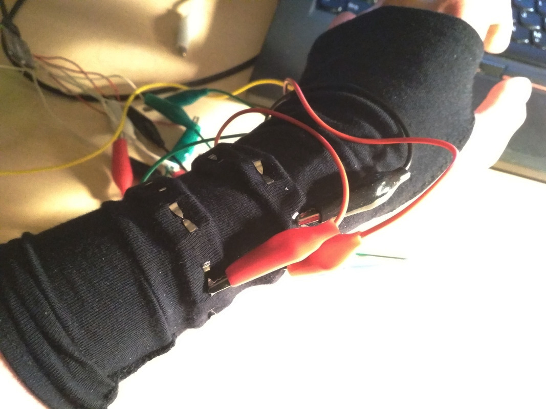
For prototype #3, I moved the electodes further down towards the wrist in hope
that I'll be able to track individual finger movements. It had 17 electrodes,
2x8 going around the wrist, as well as a ground electrode at the lower palm.
Only 9 of the 17 electrodes are connected, 8 directly to the ADC pins, and one
to 1.65V, which I created through a
voltage divider using
two 560kΩ resistors between the 3.3V and GND pins of the Arduino, so that the
electrode signals will nicely oscillate around the middle of the input voltage
range.
It all started out like a piece of goth armwear:
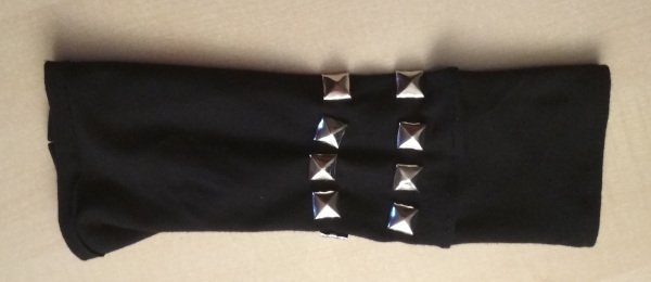
Photo from the testing period:
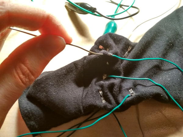
Soldering wires to the electrodes:
The "opened" state shows the components of the device:
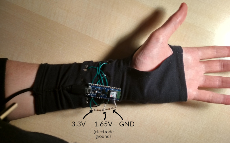
But it can be covered by wrapping around a layer of cloth, turning it into an
inconspicuous fingerless glove:
If you look hard at this picture, you can see the LED of the Arduino glowing
through the fabric, the voltage divider to the right of it, appearing like a
line pressing through the fabric, the ground electrode on the lower right edge
of my palm, and the food crumbs on my laptop :)
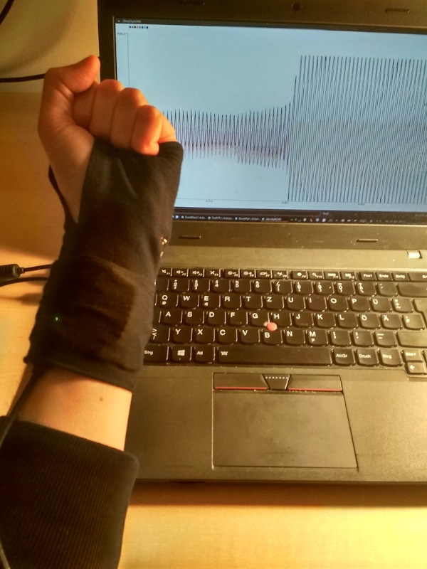
The signal seems to be much better, and as I move my arm and hand around, I can
see distinct patterns using the Arduino IDE signal plotter, but for some reason
the neural network doesn't seem to process it as well. Will need some
tinkering. I hope it was not a mistake to leave out the electrodes at the
upper forearm.
I already ordered parts for the next prototype. If all goes well, it's going to
have 33 'trodes using analog multiplexers. The electrodes will be more
professional & comfortable as well. Can't wait!
Data Cleaning
└2021-04-14, by Roman
The arduino
code
now produces samples at a consistent 1kHz. I also moved the serial read
operations of the calibrator software into a separate
thread
so that it doesn't slow down on heavy load, causing the buffer to fill up, and
the labeling to desynchronize. I am once again confused and surprised that I
got ANY useful results before.
I disconnected analog input pin 7 from any electrode, and used it as a baseline
for the other analog reads. By subtracting pin 7 from every other pin, the
noise that all reads had in common was cancelled out. Hope this doesn't do
more harm than good.
I also connected the ground line to one of the wrist electrodes rather than to
the palm, since the palm electrode tended to move around a bit, rendering all
the other signals unstable.
And did you know that the signals looks much cleaner when you unplug the laptop
from the power grid? :p
I'll finish with a video of me trying to play the frustrating one-button
jumping game Sienna by flipping my
wrist. This doesn't go so well, but maybe this game isn't the best benchmark
:D My short-term goal is to finish level 1 of this game with my device.
Multiplexers
└2021-04-15, by Roman
The analog multipexers (5x DG409DJZ) and other stuff arrived! I almost bought a
digital multiplexer, because I didn't know there were various types... But I
think that these will work for my use case. The raw signal that I get out of
it looks a little different, but when I filter out the low & high frequencies
with
TestMultiplexer2.ino,
the direct signal and the one that goes through the multiplexer looks almost
identical =D.
Amplifiers
└2021-04-19, by Roman
I have the feeling that before building the next prototype, I should figure out
some way of enhancing the signal in hardware before passing it to the
microcontroller. It's fun to hook the 'trodes straight to the ADC and still
get results, but I don't think the results are optimal. So these days I'm
mostly researching and tinkering with OpAmps.
First Amplifier Circuit
└2021-04-24, by Roman
I had my head stuck in electronics lectures, datasheets, and a breadboard to
figure out a decent analog circuit for amplifying the signal. It sounds so
straight forward, just plug the wires into the + and - pin of an operational
amplifier, add a few resistors to specify the gain of the OpAmp, and feed the
output to the analog input pin of the Arduino... But reality is messy, and it
didn't quite work out like that.
Here's a list of problems:
- The voltage I measured from the electrodes seemed incredibly fragile. As soon
as I wanted to do something with it, it seemed to change. This could be due
to the high impedance of the skin, causing a drop in voltage as soon as one
draws any current.
- One electrode may have a DC voltage offset compared of the other electrode.
When this gets large (~50mV+), the amplified voltage difference gets off the
scale.
- The OpAmp amplifies not just the signal but also the noise, like:
- I ordered a part that requires min. +/-2.25V. The Arduino supplies 3.3V, so
all is well, right? Nope. It means that I need negative 2.25V as well as
positive 2.25V.
- Solution: Increased the voltage of the entire circuit to 5V, which
the Arduino conveniently supports by changing a solder jumper. The
middle-ground reference voltage rose from 1.65V to 2.5V, leaving enough
room for the required +/-2.25V. I don't actually use the part yet, but I
wanted to prepare for it.
- The 2.5V reference voltage from the voltage divider
strongly fluctuated, messing up the output from the OpAmp.
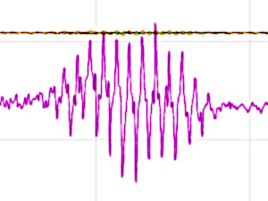
- The LM324N OpAmp that I used has an output voltage limit of 3.6V (at a supply
voltage of 5V.) That cuts off a good chunk of the signal.
- Solution: I added a second reference voltage at 1.66V so the output
centers around that. (Conveniently, the output limit of 3.6V is close to
the Arduino's ADC reference voltage of 3.3V.)
- Should I even do any of this? I'm limiting the neural network by introducing
my bias about what a clean signal looks like. Any circuit will invariably
filter out certain information, enhance other information, and add irrelevant
noise. How do I know that the information that I filter out (e.g. the DC
offset voltage between electrodes, or even what I consider irrelevant noise)
isn't useful to the neural network?
- Solution: Keep the signal processing reasonably minimal
I also connected the electrode signal to ground with a 1MΩ resistor which
greatly improved the signal, and I have no idea why.
One peculiar thing I noticed was that the signal seemed stronger when my laptop
was connected to the power supply. It superimposed noise, but also seemed to
increase differences in electrode voltages. I don't quite understand this yet,
but 2 things follow from that:
- For replication purposes, I'm using a Lenovo Thinkpad T460p switched to the
Intel GPU, which creates it's own particular noise patterns, even when
unplugged from the grid.
- I should try out modulating the ground electrode voltage with a controlled
low frequency pattern to see if this improves signal to noise ratio. Ideally
<30Hz or >500Hz so I can easily filer it out later.
Some of the references I used:
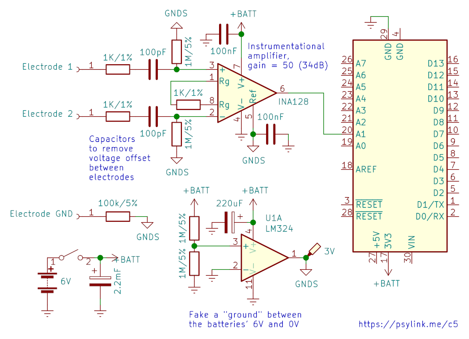
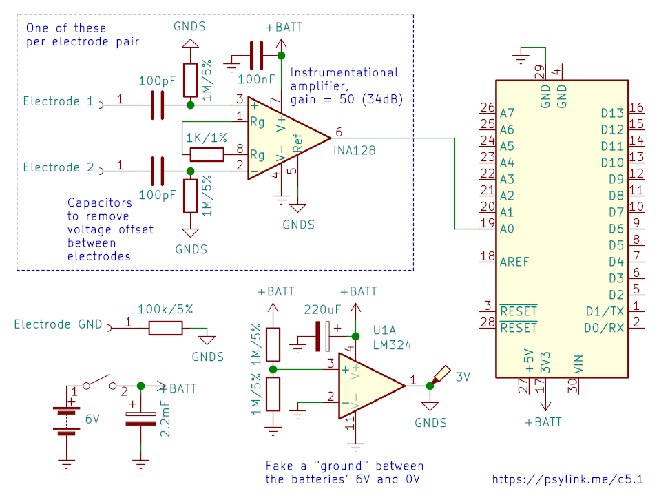
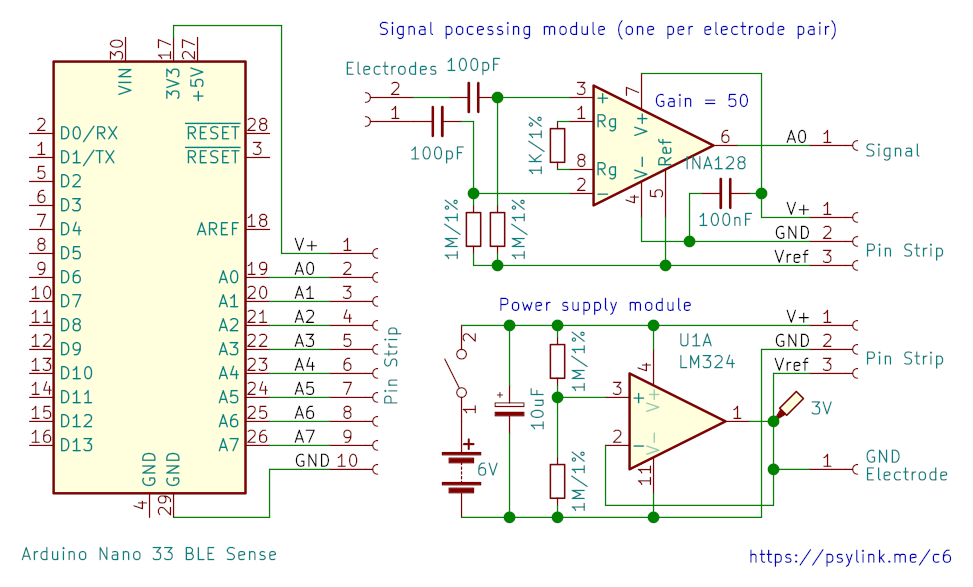
The resulting circuit:
And the signals look like:
Yellow and green are two electrodes, right after their respective OpAmp, and purple is (yellow-green)*20.
This should be good enough to move forward, but I bought some INA128 instrumentation amplifiers and perhaps I will tinker some more to get an even better signal. Can't wait for the next prototype though :).
In other news, I watched Dr. Gregory House explain forearm muscles, so next time my electrode placement will be better than random!
And since I learned KiCad for creating the above schematic, I thought I'd add schematics for the previous models as well, see circuits.
Going Wireless
└2021-04-28, by Roman
I've been battling with reducing the power line noise for too long, so I
thought screw it, let's go off the power line entirely. I put the circuit on
two 3V CR2032 coin cells and wrote
some code
to transmit the signals via BLE (Bluetooth Low Energy) using the
ArduinoBLE library.
Since I can not plot the signals via the Arduino IDE plotter anymore, I
switched to GNURadio and wrote a plugin that
establishes the BLE connection and acts as a signal source in the GNURadio
companion software
My new "electrodes" also arrived: Simple prong snap
buttons.
They don't have sharp edges like the pyramidal studs I used before, and allow
me to easily remove the wires from the electrodes and plug them in somewhere
else as needed.
I also employed INA128 instrumentation
amplifiers, drastically reducing the
complexity of the circuit. It's a tiny SMD chip, which I plan to embed in hot
glue, along with the 3-4 capacitors and 3-5 resistors required for
processing/de-noising, and place 8 of these processing units across the
glove/wristband, connected to two electrodes each.
Now I'm battling the problem that I can only get about 1kB/s across the ether.
How am I supposed to put 12kB/s worth of signal in there? (8 channels,
1k samples/s, 12 bit per sample) Let's see if I can find some nice compression
method, but I fear that it's going to be lossy. :-/
Soldering the Processing Units
└2021-04-29, by Roman
The plan was to split the circuit into:
- 1 central part including the Arduino, power supply and the OpAmp that
generates the signal ground, and
- 8 distributed signal processing units, embedded in hot glue for stability and
electrical insulation, consisting of an instrumentation amplifier and related
components, close to the electrodes to avoid signal degradation.
Here's my try to solder one of those units:
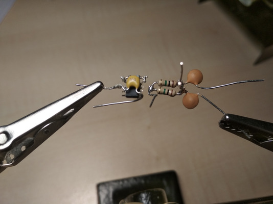
This took me over an hour, during which I began questioning various life
choices, started doubting this whole project, poured myself a Manhattan
cocktail, wondered how long it would take to complete all eight of these,
whether it will even be robust enough to withstand regular usage of the device
(NO, IT WON'T), and how I'm going to fix the inevitable broken solder joints
when the entire thing is in fucking hot glue...
I gave up, and now my plan is to get
PCBs for this instead.
I have little experience with this, so I've been putting it off, but how hard
can it be?
First draft:
Updated schematic:
I removed the decouplying capacitor between ground and GNDS (signal ground) by
the REF pin of the INA128 because mysteriously it made the signal worse, not
better. Also removed the 1K resistors between electrodes 1+2 and the
respective capacitors, because they served no apparent purpose.
Also, I was frustrated that GNURadio doesn't allow you to get a "rolling" view
of a signal. The plot widget buffers as many samples as it can show, and only
when the buffer is full, it updates the graph, clears the buffer and waits
again.
I wanted instant updates as soon as new samples are in, and as a quick&dirty
workaround I wrote a
GNURadio shift block
which keeps filling up the buffer of the plotting widgets.
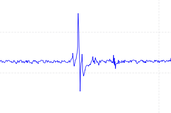
I'll finish with a nice picture of a finger snap, as recorded with one
electrode pair on my dorsal wrist. Click to enlarge and view the frequency
domain as well. (Just one electrode pair because that's all I can squeeze out
of the poor bluetooth low energy bandwidth so far)
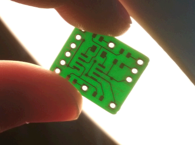
PCB Time
└2021-04-30, by Roman
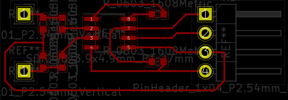
Today I made a new version of the PCB that processes the signals from one
electrode pair:
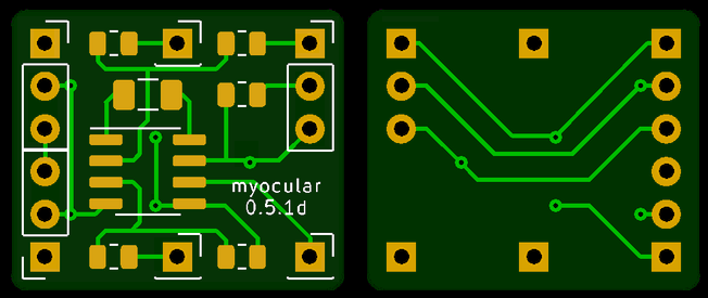
Actually, several versions. This is the 4th iteration, and let's not even look
at the previous ones because they were just plain wrong. I stared at this
design for a long time though and couldn't find another problem, so I went
ahead and ordered 30 pieces of it. Can't wait to find out in what way I messed
up :'D And hey, maybe it'll actally work.
Main features:
- Dimensions: 20x17x1.6mm, rounded corners
- Tiny enough to fit between 2 electrodes!
- 2 connectors for electrodes, at the middle top & bottom
- 1 connector for the output at the bottom right corner (on the front side. The back
side is mirrored)
- 3 power line connector ports on the other corners, with 3 pins each:
- The signal reference voltage
- Ground
- +6V from the battery
- 3 capacitors, 3 resistors, 1 integrated circuit
To avoid having a kilogram of cables on the device, this board supports wiring
in a mesh network topology,
where the boards share the power lines amongst each other using the redundant
power line connector ports. One board can power two other boards, which in
turn can power 4, and so on.
The bypass capacitor between ground and V+ will hopefully keep the voltage
stable, though I'm a bit worried about the reference signal. If necessary, I
can "abuse" the reference signal pin of the power line connector ports to add
extra ground electrodes. I considered adding an extra opamp on every board to
generate a fresh reference voltage but that would make the circuit too big for
my taste.
Higher Bandwidth, new UI
└2021-05-04, by Roman
Hah, I managed to raise the Bluetooth bandwidth from ~1kB/s to 6-7kB/s with this one magic line:
BLE.setConnectionInterval(8, 8);
It raises the power consumption by 4% (3.5mW), but that's totally worth it. I
can now get all 8 channels in 8-bit resolution at 500Hz across the aehter.
Eventually I should aim for 10-bit at 1kHz, but I think that can wait.
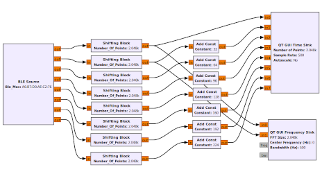
This is the GNURadio flowgraph
and the resulting output. (I only have hardware for 2 electrode pairs, so
even-numbered and odd-numbered signals are wired to the same input. Still
waiting for the PCBs.)
Power ratings:
- No Bluetooth connection: 86.9mW (16.9mA x 5.14V)
- Transmitting at 1-2kB/s: 88.9mW (17.3mA x 5.14V)
- Transmitting at 6-7kB/s: 92.5mW (18.0mA x 5.14V)
Surprisingly to me, the LEDs were draining a good chunk of the power, and I
saved 16mW by removing the external power LED (see previous
photo) and by
PWM-dimming
the blue LED that indicated Bluetooth connections. It gives me approximately 15
hours run time with 2x CR2032 coin cells.
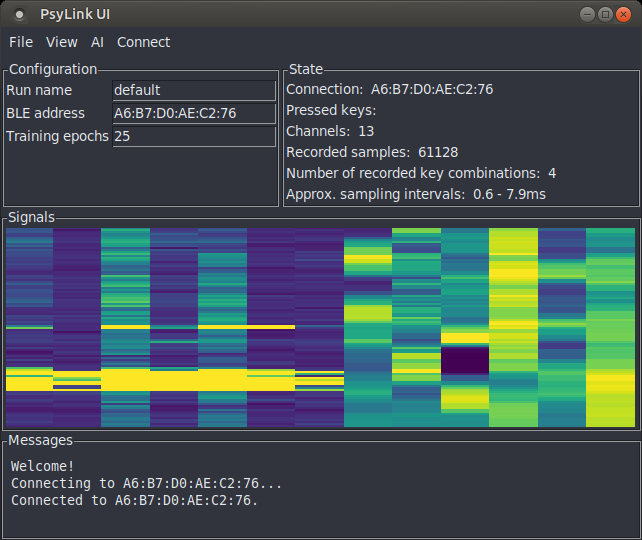
Also I'm in the process of rewriting the UI:
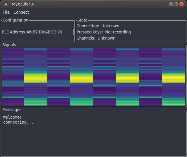
The colorful column graph is a live visualization of the signal. The columns
correspond to electrode pairs, while the rows are time frames. The top row
shows the amplitude of the signal at the current time, and the rows flow
downward, allowing you to view changes back in time, as well as correlations
between signals.
You'll also be able to change settings on the fly, view the status of e.g. key
recordings or machine learning processes, and more. All of this is in a
modular library
that will also be usable from e.g. GNURadio.
I was thinking of changing the graphical user interface toolkit from Tkinter to
a more modern one, because Tkinter looks a little shabby, and it has problems
determining which keys are currently pressed, but I decided against it, because
I made the experience of being unable to run my own software several years
after writing it because the exact version of the GUI toolkit, along with all
dependencies, was too annoying to set up. Tkinter has been around for decades
and will probably stay, so I'll stick with it for now. Also, I can easily
solve the key pressing issue with an external key tracking library like
pynput.
Can't wait to try out the new UI with 8 individual electrode pairs, once the
PCBs arrive! (assuming they work :'D)
Finished new UI
└2021-05-06, by Roman
The new user interface now supports all previous features!
- Capturing muscle signals
- Capturing the keys that the user is pressing
- Training a neural network to predict key presses from given signals
- Auto-pressing keys based on incoming signals using said neural network to
predict which keys the user wants to press
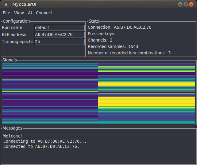
It's sooo much more pleasant to have a direct view on the state of the
application and an instant visualization of the signals. The previous version
was literally just a blank window, with a single menu called "File" that
contained all the actions. :D I never even bothered to upload a screenshot,
but here's one for documentation purposes:
Also, this time I used clean & efficient data structures to make the code
easier to work with, a more reliable key capturing library
(pynput), and threads to prevent one
activity from blocking the others. The signals obviously go via Bluetooth
instead of a wired serial connection.
I'm also thinking of changing the name for the project, since people are
reading it as "my ocular" rather than recognizing the neologism made of "myo"
(for "muscle") and "ocular" (from "eye"). But all the good names are taken, of
course. -_-
New Name
└2021-05-07, by Roman
After some brainstorming, I changed the working title of this project from
Myocular to ✨PsyLink✨. The close second favorite was FreeMayo (thanks to
Vifon for the suggestion). Free as in free speech/software/hardware, and mayo
as a play on myo (ancient greek for "muscle"). But somehow I liked PsyLink
more. It's inspired by the Psionic
Abilities from the
1999's game System Shock 2.
FYI, this is the list of words that I considered, although unfortunately many
of the coolest combinations were taken:
- axon
- coil
- cortex
- cyber
- free
- gauntlet
- glove
- link
- loop
- magic
- mana
- mayo
- myo
- open
- pipe
- plug
- psi
- psionic
- psy
- psyber
- scan
- surge
- tron
- ware
- wave
- wear
Power Supply Module
└2021-05-09, by Roman
I made an updated schematic (circuit 6) that shows more clearly how the modules
are connected. Also corrected an error with the feedback of the voltage
follower, and changed values of some resistors/capacitors:
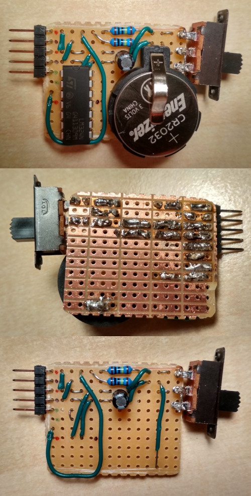
I also constructed the power supply module:

but for some reason it didn't work. All the parts seemed to have been connected
the right way, I couldn't find a short circuit, but the output voltage was
~0.5V instead of ~5V, and the reference voltage was just 0. I blame a possibly
broken opamp.
Well, I didn't like the design and length of the circuit board anyway, so it
didn't hurt trashing the thing and building this beauty instead:
I'll use female-to-female jumper wires to connect V+ and GND to the arduino,
and 3 more wires to bootstrap the power supply of the mesh network of the
signal processing modules.
Notes:
- Yep, that's 2 coin cells in there
- Outputs: Black=Ground, Red=V+, Green=V+/2 (reference signal)
- There's an optional second green pin for the ground electrode
- If you're wondering why I'm using a big ass quad opamp when I just need a
single output: I don't have a smaller one atm.
- I totally need to move this to a SMD PCB in the long run, this is still too
bulky, but will do for now. It's about the dimensions of a 9V battery.
I wonder if some 深圳人 will read this, shake their head, and view me as
a primate struggling to make fire with sticks. That's what it felt like
to construct this thing anyway. Nevertheless, I'm one step closer to the next
prototype :)
Wireless Prototype
└2021-05-14, by Roman
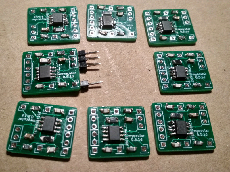
Hell yeah! The PCBs arrived:
Soldering & Sewing
I never soldered such tiny SMD parts before, and didn't have proper tools, way
too thick soldering tin and solder iron tip. I was also too impatient to order
some, so after hours of torture, I produced this batch:
The new prototype was to be a forearm sleeve of modal fabric once again, with
snap buttons for electrodes which will also hold the signal processing PCBs in
place.
But how to attach the Arduino and the power supply module to the sleeve? I
thought, "why not Velcro?" (hook-and-loop fastener) and started sewing it to
the circuit boards:
(Yes, doing it felt as weird as it looks)
So I sewed the sleeve, assembled one electrode pair along with its processing
PCB, and wired everything together. Here's me being overly excited about the
first wireless test run:
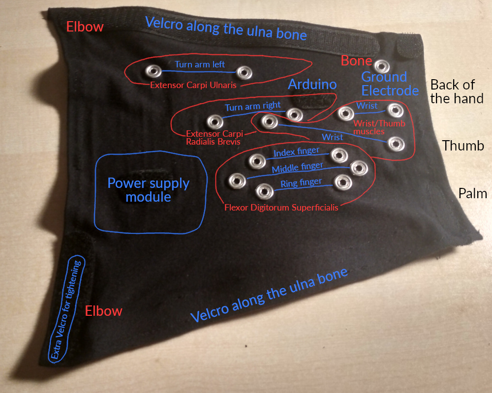
Electrode Placement
Then there was the question of where to put the electrodes. Using an
improvised muscle map along with two flexible electrodes on individual straps,
I could find spots whose electrical activity correlated with turning the arm,
twisting the wrist, or pressing individual fingers onto the table:

Flexor Digitorum
Superficialis
was particularly interesting; I found 3 areas over that muscle which map to the
index, middle and ring finger each. For turning the arm and wrist, the muscles
with "Carpi" in their name (e.g. Extensor carpi
ulnaris) worked
pretty good.) A huge disappointment was Extensor
Digitorum,
which is supposed to be active when fingers move up, but I could not find such
correlation. Then again, I use snap buttons for electrodes, so I'm not that
surprised.
The final layout of the electrodes:
This piece is fully separable from the electronics and therefore machine
washable.
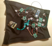
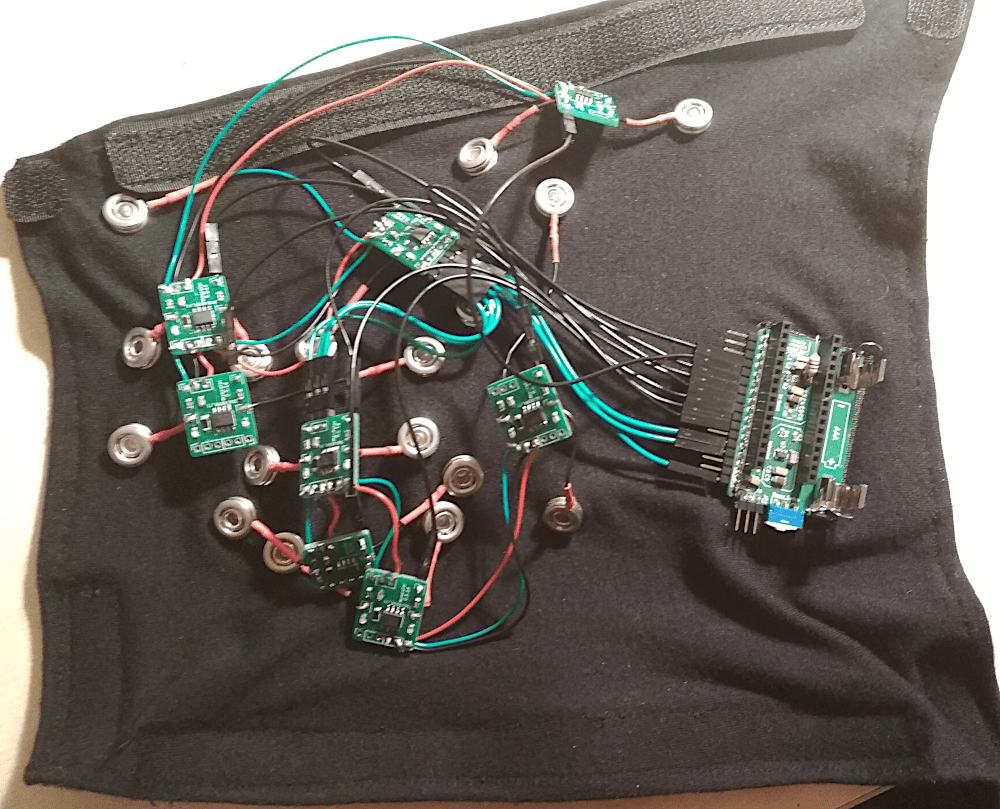
Here are additional pictures of the inner side, the separated electronics, as
well as everything combined. This nicely shows the tree topology of the green
signal processing modules that pass through the power supply among each other
to reduce the volume of wiring.

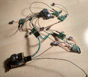
I could have had 8 electrode pairs, but only added electrodes for 7. On these
pictures, the electrode pair for the middle finger is also missing the
circuitry. That's mostly a testament to my laziness.
Actually I regret where I placed the Arduino, since there would be some great
spots for electrodes, but I noticed that too late. Will try to remove the
Velcro and maybe add an 8th electrode pair there.
The final cyb3rware:
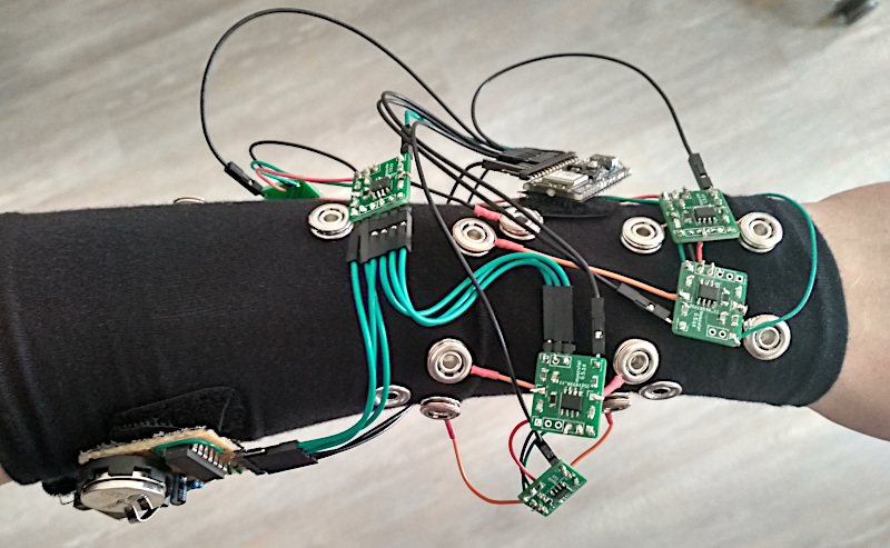
While the signal was quite strong with the test straps, I found that the
amplitude of the signal went way down once I had everything attached to the
sleeve. Maybe there was some kind of interference from the Arduino or the
power supply being closer to my skin, or maybe the modal fabric messes with the
signal somehow. I hope I can compensate for this by increasing the signal
amplification multiplier, but I leave that for later.
This issue occurred with a single electrode pair already, but was aggravated
when attaching more of them. It might help if I add some flux capacitors to
the power supplies to prevent cross-interference.
Test Drive
I drove F-Zero with Prototype #2 before, but back then I
cheated a little bit. It only recognized 2 keys, left and right, and I
accelerated with the keyboard using my other hand.
This time I hoped I could do better, and trained the AI to recognize 3
different keys (left, right, accelerate) from my muscle signals. It even
kinda worked!
This was after recording ~2000 muscle signal samples over 1-2 minutes and
training a convolutional neural network for 25-50 epochs (<1 minute) on the
data using the PsyLink
UI.
I used 4 electrode pairs, all of which are on the dorsal side of the forearm.
Analysis
In the racing game, I didn't make it to the finish line yet, and it does look
pretty clumsy, but I blame it on the software still having some obvious flaws.
It doesn't even account for packet loss or packet duplication when handling the
Bluetooth packets yet. Hope it will go better once I fixed them. Also, the
test drive was with only 4 electrode pairs.
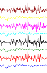
The raw values as visualized with the GNURadio
flowgraph
while randomly moving my forearm/wrist/hand show that the correlations between
the signals are low enough to be theoretically useful:
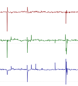
If you enlarge this image, you'll see that especially the black line is
considerably different, which I suppose is because it's the only electrode pair
that spans across several muscles. And that makes me wonder: Am I doing too
much pre-processing in hardware before I feed the data into the AI? Sure, the
differential amplification of this new prototype enhances small signals that
the previous prototypes might have not detected, but a lot of information is
lost too, like the voltage differences between electrodes from different
electrode pairs.
Maybe I can compensate for this by simply adding some more electrode pairs that
span muscles. I'm also thinking of switching to a design with 32-64 randomly
placed electrodes -> buffer
amplifiers
-> multiplexers
-> analog to digital converters of the Arduino. That way, the neural network
can decide for itself which voltage differences it wants to look at.
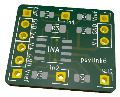
New PCB layout
While soldering the PCB, I found some flaws and made these changes to the
previous PCB:
- Added silkscreen labels to the connectors and components. I was sure I
wouldn't mix up anything since there aren't many connectors, they're nicely
symmetrical, and I'm the designer after all. But nope. I still mixed them
up.
- Removed unnecessary vias.
(I was actually not sure whether the pin holes will really conduct between
the front and the back side of the board, so I added vias as a safety
measure.)
- The label now shows the new name "psylink" instead of "myocular"
- A friend also gave me the tip to increase the thickness of power supply wires
Gyroscope + Accelerometer
└2021-05-17, by Roman
I fixed up the PsyLink UI. It was so broken after the rewrite to Bluetooth Low
Energy, I'm once again stunned that I got ANY useful results before. But now it
receives the transmissions from the Arduino properly.
I also added 6 more signal channels: The x/y/z-axes from the Gyroscope and
from the Accelerometer that are built in to the Arduino Nano 33 BLE Sense.
All put together finally allowed me to singlehandedly drive through the finish
line of my favorite racing game F-Zero! \o/
- For training the AI, I recorded 60k samples over 2 minutes (500Hz)
- Trained for 5 epochs, which took 1 minute without GPU acceleration
- 4 training labels ("left", "right", "accelerate", "nothing")
- Final training and validation loss: 0.04, accuracy: 98%
- 6 layer neural network with 2 convolutional layers
- Music by Mitch Murder
Dedicated Website
└2021-05-29, by Roman
The PsyLink project now has it's own website: psylink.me,
and this is the place where I will continue the development log, as soon as I
finish the basic structure of the website.
Website is Ready
└2021-05-31, by Roman
The website is more fleshed out now, with a nice black/green design, neurons in
the background, and a logo that is based on the logo of the fictional
TriOptimum Corporation
from the System Shock game series.
Videos are now hosted on a PeerTube
Channel,
allowing me to upload higher quality videos in the future while keeping the
git repository of the website
small.
I also catalogued individual components (circuit schematics,
circuit boards, textiles, software) that
resulted from this project so far, and documented how they all fit together in
the prototype overview. Each component has an individual ID
now, that I can easily write, print or sew on the hardware so I don't mix
everything up. For example, prototype 4 has the ID "p4" and can be reached
directly via https://psylink.me/p4, while the signal processing board of
p4 has the ID "b1" and can be reached via https://psylink.me/b1.
Here's a screenshot, for a future time when the design has changed:

Back to the Roots
└2021-06-04, by Roman
While uploading the old videos to the new PeerTube
channel, I
viewed the first
video
once again, which shows a pretty good signal from just two pieces of aluminum
foil taped to the skin. And I wondered, why do I even bother with such a
complicated set-up like in Prototype 4? It was really annoying to
assemble, and the device is clunky and fragile.
Let's go back to the roots and build something more simple. Plenty of reasons:
- Having 8 small, distributed signal processing PCBs sounds nice at first, but
it creates more points of failure. With Prototype 4, I had multiple
instances where a connecting wire broke off, so this time I'd rather have
everything on one PCB.
- What happened to the idea of processing the signal as little as possible and
leaving the job to the neural network? Circuit 6 (whole device) amplifies certain
information but hides other, like the DC voltage offset between electrodes.
- The electrode map of Prototype 4 provides me with signals (like "arm
turns left/right") which are redundant since I added support for the
inertial measurement unit (IMU).
- The signal from the IMU is actually way more reliable than what I'm
getting from the electrodes, so why not ditch them completely? Well,
there are some parts of the arm that move separately from the Arduino,
mainly the fingers. So let's focus on these.
- My main issue with the early prototypes was the poor signal-to-noise ratio,
but that was mainly due to the power line. This should be gone with a
battery-powered device.
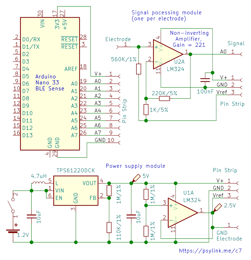
Circuit 7
The Circuit 7 (whole device) shows a simplification of the signal processing module to
a simple non-inverting amplifier per electrode with a gain of 221x. There's
also a 560KΩ bias resistor towards Vref so the voltage we measure isn't too far
off the center. In Circuit 6 (whole device) I had used 1MΩ, but here it produced
mysterious oscillations, and going
down to 560KΩ mysteriously fixed it.
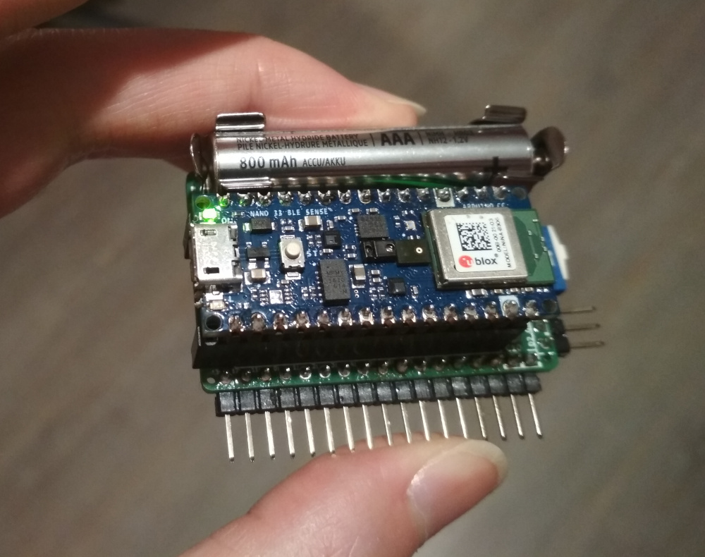
This circuit also features a rechargeable 1.2V AAA battery with a TPS61220
step-up converter boosting the voltage to 5V, because I don't hate nature, and
I burned through enough CR2032 coin cells. Coin cells also aren't exactly
optimized for currents of 20mA, and thus get drained too quickly.
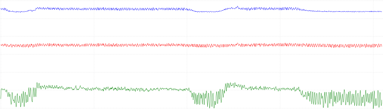
I measured a signal while pressing down a finger onto the table with two
electrodes along the Flexor Digitorum Superficialis. Blue is electrode 1,
red is electrode 2, and green is an amplified difference:
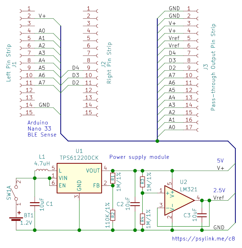
Circuit 8
But let's cut even more out of this circuit. Here's one that is designed to be
a shield to the Arduino Nano 33 BLE Sense, containing just the power supply,
and an array of pass-through pins:
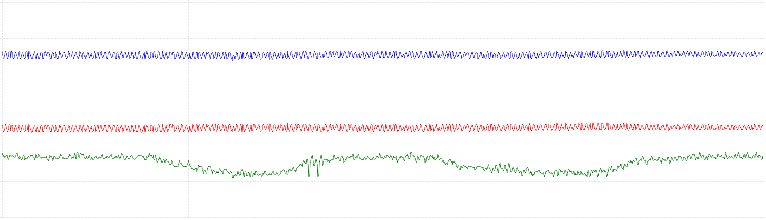
The signal that I'm getting is weaker, but certainly usable: (again, I measured
a signal while pressing down a finger onto the table with two electrodes along
the Flexor Digitorum Superficialis. Blue is electrode 1, red is electrode
2, and green is an amplified difference)
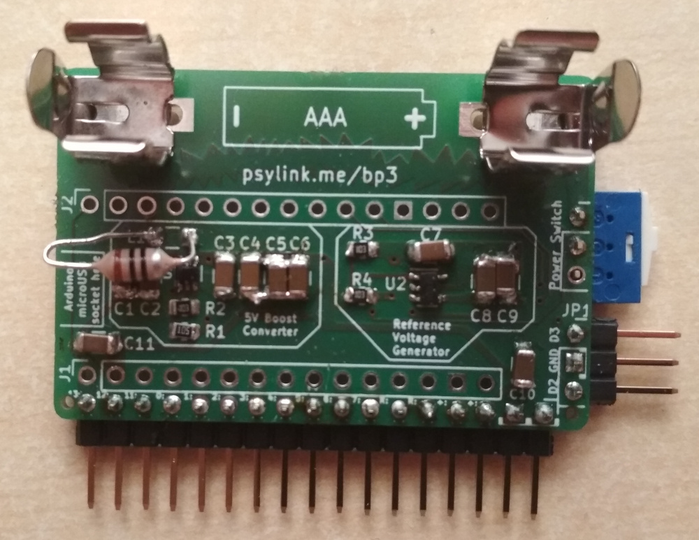
PCB
I also built a PCB that implements this power supply/pass-through shield, and I
figured, even if the device ends up not very useful, I'll still be able to use
this for experiments later on, thanks to the pass-through pins.
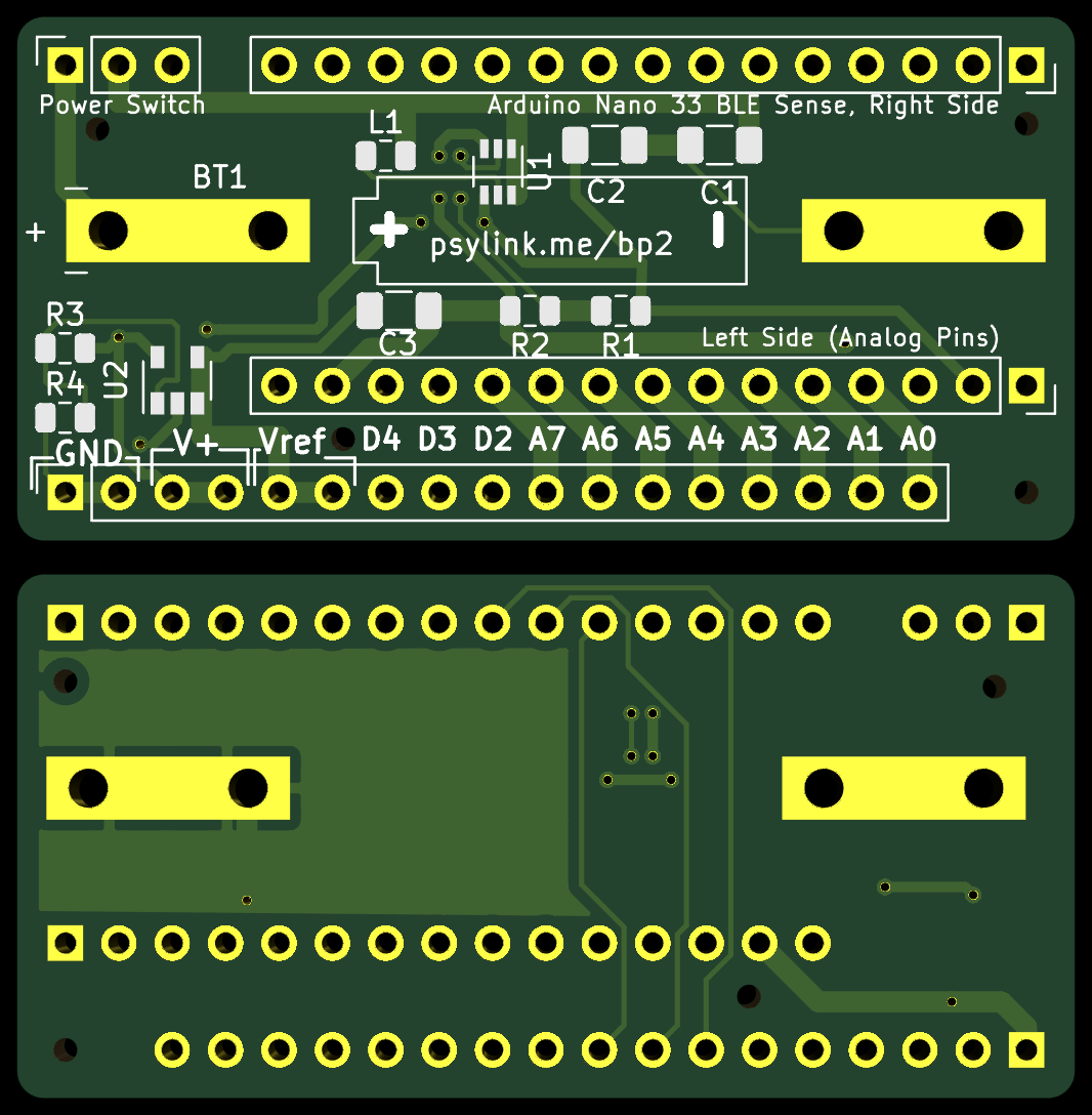
I just hope that the PCB/circuit will work at all. I still haven't figured out
how to simulate it, and I don't really know the best practices for PCB design.
The PCB footprint for the AAA battery clips (Keystone 82) is my first
custom-made PCB footprint too. Hope it all works out.
Next Prototype
It will be a relatively small forearm band with 8 electrodes (+ 1 ground
electrode), which I plan to place around the Flexor Digitorum
Superficialis
for detecting what individual fingers are doing. The information from the
gyroscope + accelerometer should cover the rest.
Believe The Datasheet
└2021-06-10, by Roman
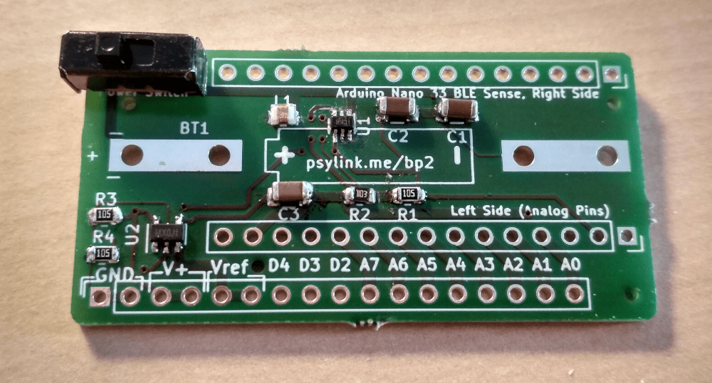
Today the order of Power Module 2 arrived!
And with relief I saw that the battery clips fit nicely onto the board, as does
the Arduino (with pin strips), and all the other components. Just that simple
thing already felt like an accomplishment at my level of expertise with
PCB design ;)
After some dreadful time trying to solder on the tiny 1x2mm-sized chip at U1 (I
need a microscope for this shit), I had the SMD parts assembled and the circuit
was ready for a test drive:
But something was weird. The output voltage was a meager 1.5V, not the
expected 5V, even though everything was connected properly. After hours of
debugging I flipped over the table and just soldered a fresh board, this time
without the Vref-generating OpAmp (U2+R3+R4+C3). But no luck, still just 1.5V.
This was lower than the minimal output voltage of the voltage booster, so the
chip didn't even finish it's start-up phase. How could that be, if there's not
even any load on the output voltage?
I desperately tried several different things. One was doubling the inductance
at L1 from 4.7µH to 9.4µH by using two SMD inductances in series:
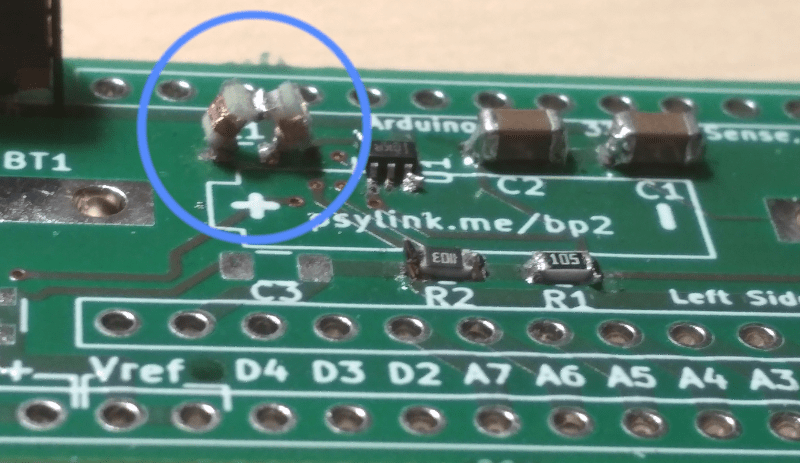
Unfortunately I think I broke the coils while constructing this, since they
didn't let any current go through. But I found a regular, big inductance coil
with 10µH, manually held its pins down onto the SMD pads, and indeed, the
voltage jumped up to 5V!
So I soldered it... onto... the SMD pads.

(Probably you can reconstruct my entire room from all the reflections in this
image, along with a biometric picture of my face and at least 3 of my
fingerprints...)
But once I connected the OpAmp, the voltage went back down to 2.5V, and with
the Arduino connected, it went down further to 2.4V. Adding a second coil in
series for a total of 20µH didn't compensate for this, but made it even
worse, bringing it all the way down to 1.5V.
Well, clearly whatever is wrong with this construction has something to do with
the inductance, and it's not purely the amount of inductance... Which brings
us to the title of this post:
The mistake (probably)
Of course the data sheet of the voltage booster CLEARLY STATED that the
inductance coil needs to be AS CLOSE AS PHYSICALLY POSSIBLE to the chip. The
capacitors C1 and C2 too, by the way. And I even read that. But I thought,
what could possibly go wrong if I move it ~1cm away to make some space for the
battery? Nothing, right? Well, awesome, I guess it's time for another
revision :)
At least the 2.4V were enough to power the Arduino, although it was visibly
struggling. I could establish a Bluetooth connection and collect some signals,
but the Bluetooth packets were coming in extremely slowly (though still faster
than mobile internet in 80% of Germany.)
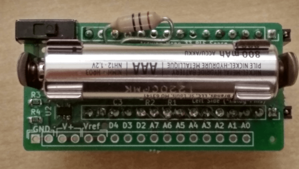
Pictures
Front:
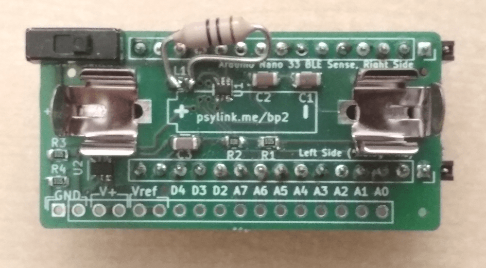
Somehow the oversized inductance coil adds a nice vibe to it.
Front, with battery:
Back, with attached Arduino:
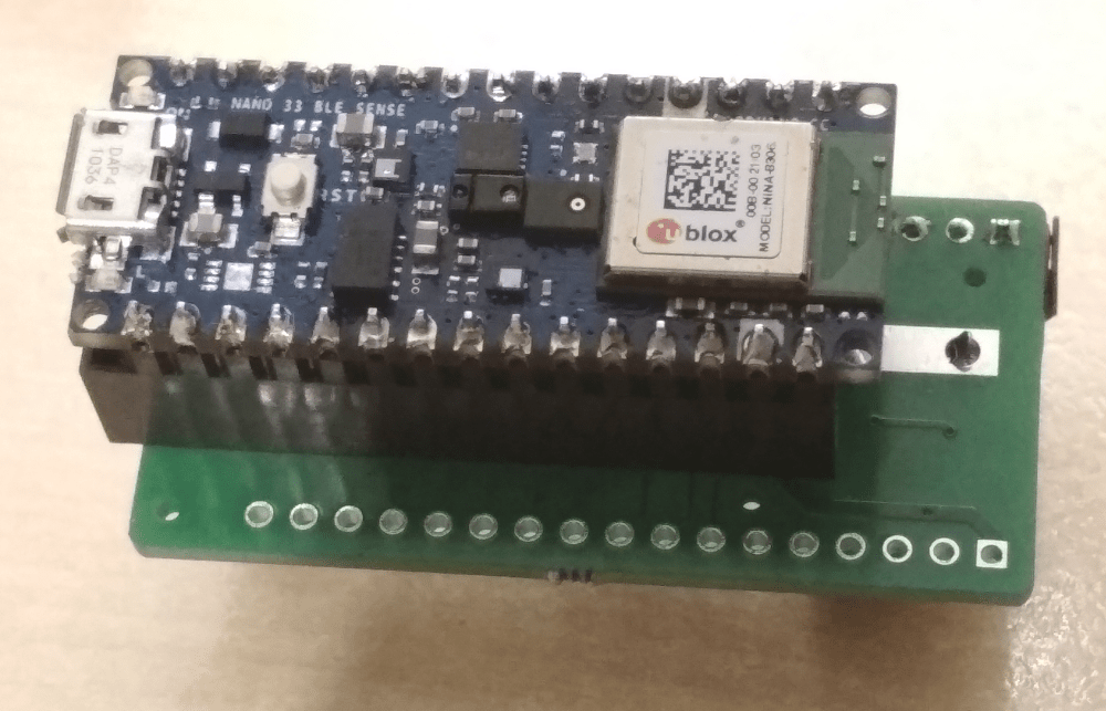
This picture shows a pin strip socket that will be gone in the final version,
where the Arduino will be soldered onto the board, reducing the height from 3cm
to 2cm.
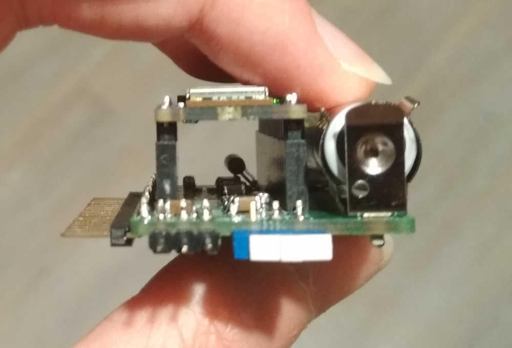
Side, with Arduino and battery:

(Yes, the pin strip socket is too long by one pin ;))
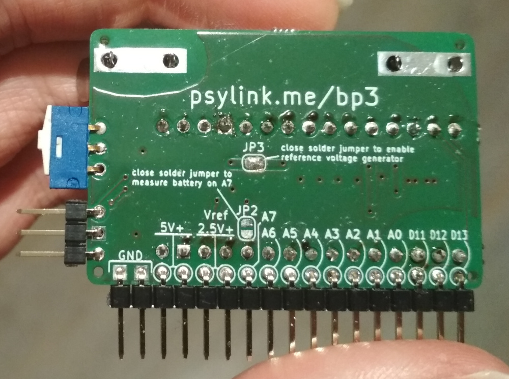
Power Module 3
└2021-06-16, by Roman
Since Power Module 2 has the wrong PCB layout for the step-up converter, I
built Power Module 3 to fix this issue.
It was still a worthwhile learning experience to build Power Module 2,
resulting in the following changes:
- Instead of stacking the Arduino and the Battery on top of each other (one on
the front side of the board, one on the back), they're now side by side, to
make the board flatter and fit better on the forearm.
- Added more capacitors all over the place
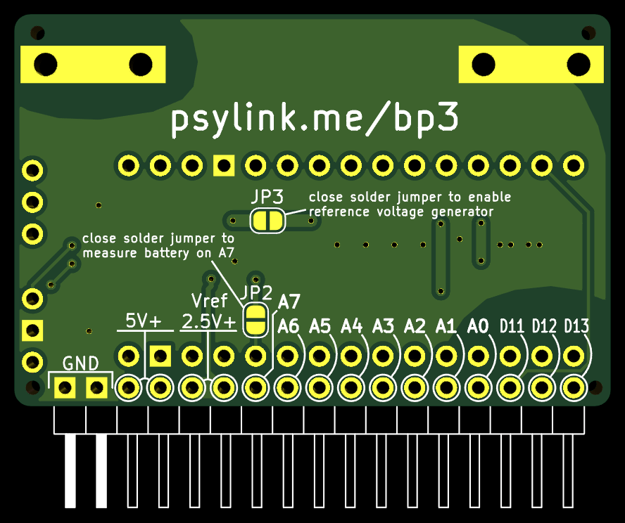
- Added various jumpers:
- A solder jumper to enable/disable the reference voltage generator, in
case I come up with a setup where I won't actually need it
- A solder jumper to sacrifice one electrode and use its analog input pin
to measure the battery charge instead.
- Three configuration pins, connectable via jumpers, to change software
settings on the fly and toggle between up to 4 different modes. Or you
can use them to plug in an extra module.
- Hopefully fixed the layout for the step-up converter
Here's the circuit:

And the new PCB:
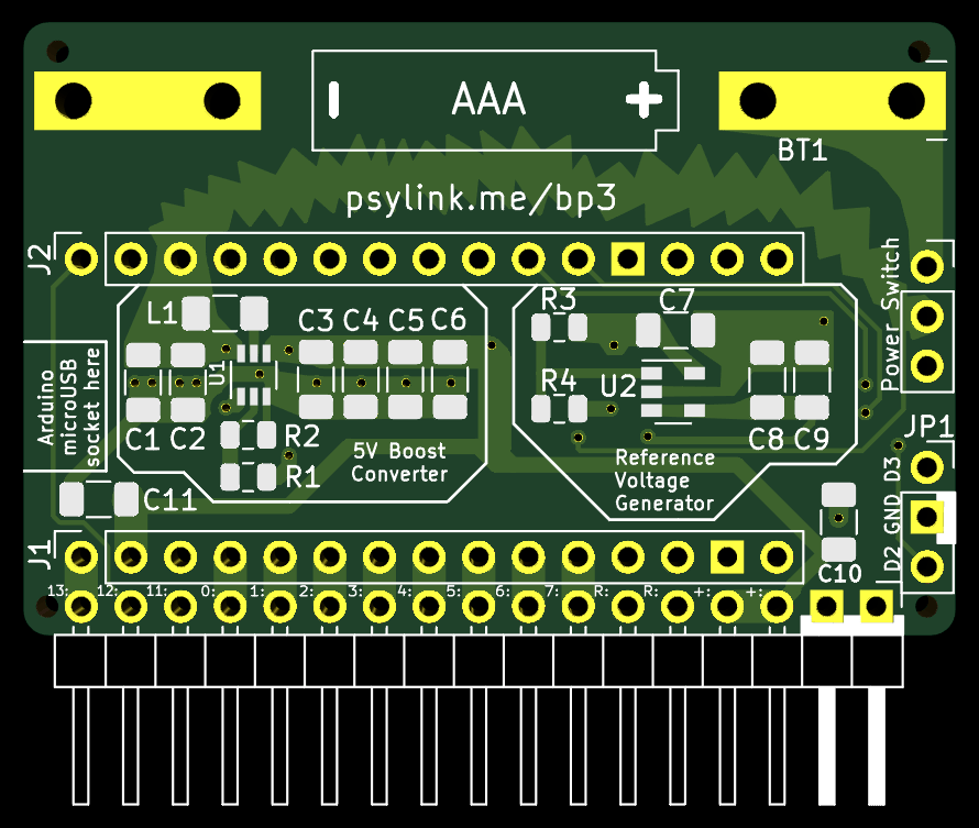
If you're wondering why the sparky, fancy looking power line goes all the way
from the power switch on the right through digital pin D10 and into L1 on the
left side... Indeed that looks pretty awkward, but L1 is the noisiest
component, and I wanted to keep it as far as possible from the analog pins at
the bottom, without sacrificing the effectiveness of the boost converter
layout. Given the size & time constraints, I didn't find a better solution.
What time constraints, you ask? Well, actually I made a different PCB layout
first. Polished every detail, and when it was perfect (according to my crude
appraisal), I ordered it. Was already excited about the delivery, started
putting the board on the website, and so on. But at some point I noticed that
something was wrong... The Arduino pins were inverted. Theoretically,
everything would still work, but the Arduino would have to be plugged in from
the back side, which is something I wanted to avoid to keep the board laying
nice and flat on the forearm...
Thankfully the manufacturing process hasn't started yet, and I could update the
board for free. So I started redesigning half of the board and finished just
in time for the production to start :D
Let's hope it works this time.
Running on AAA battery
└2021-06-21, by Roman
Wow, it feels like ages since I started working on making PsyLink run on a
rechargeable AAA battery. It sounds so simple and straight-forward, but it
wasn't :). This ate 2.5 weeks of my time, but finally I succeeded!
Coming from software engineering, the iteration time of hardware prototypes is
horribly slow. There was a lot of waiting for package deliveries, a lot of
time assembling, and a lot of wrestling with leaky
abstractions.
For example, it wasn't enough to just connect the 1.2V->5V boost converter like
on the circuit diagram, but I had to take special care of the distances between
the parts, and the widths of the copper tracks connecting them.
Another problem you never face in software engineering is that the package with
electronics parts was stolen, and when the new PCB of Power Module 3
arrived, I had to work with the few remaining (suboptimal) parts that I had.
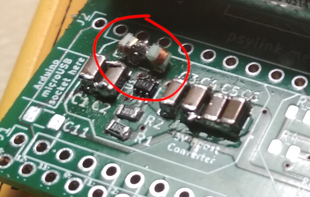
What almost drove me insane was that I had only one fresh TPS61220 chip left.
That's the 5V boost converter at position U1 (in the bottom of the red circle
on the photo below), which is so small that I don't really have the tools to
solder it on properly. I kept accidentally connecting the pins of the chip
with solder. I gave up and started asking around friends for whether they
could solder it on for me, when I remembered this soldering tip someone gave
me: If you don't have soldering flux (which I didn't have), just use
✨margarine✨ instead ;D. It sounds very wrong, but it actually made a huge
difference, and only thanks to the power of margarine I was able to keep the
solder exactly where I needed it to be. "If it's stupid and it works, it's not
stupid."
Then - for whatever reason - the voltage was going up to 1.5V instead of 5V,
just like with the previous PCB layout. I thought I fixed
that problem by optimizing the layout around the TPS61220
chip, but apparently that wasn't enough. I figured the
4.7µH inductance at L1 wasn't big enough, so I squeezed in a second coil:
(It looks like two tardigrades playing ball :) I wish I made a better picture
before I disassembled it again)
This alone didn't help, but when I manually held an additional 10µH
inductance in parallel to L1 for 1 second while the device was running, it
surprisingly kickstarted and reached 5V!... until I drained some current, which
made the voltage collapse back to 1.5V immediately. Curious behavior. :D
Then I tried soldering on the big 10µH coil directly onto the SMD pads,
and the voltage reached 5V and stayed at 5V =)
No idea why the big 10µH coil worked while the two smaller coils totaling
9.4µH didn't work... I doubt that the 0.6µH difference in total
inductance turned the tide, probably there's some factor I'm not aware of. I
actually had ordered a 10µH SMD inductance coil in anticipation of this,
but well, it got stolen... My only consolation is the face of the package
thieves when they open the package, they realize that it's just a couple of
tiny SMD parts, and they wonder WTF this shit is even good for.
P.S.: I found out that the reason why the coils didn't work was that they were
not rated for the >200mA that's passing through them. Once I got a 4.7µH
coil rated for 280mA, everything was fine.
More pictures:
The lack of parts forced me to adjust the resistance/inductance/capacitance
values of Circuit 9 (power):

Thankfully I had planned for way too many capacitors on the PCB, just for some
extra VROOOM, so the fact that I only had 10µF capacitors instead of the
planned 100µF didn't matter too much.
I also changed the 1MΩ resistors in the reference voltage generator to
110kΩ because I read that smaller resistances in a voltage divider make
the output voltage more stable, at the cost of more power use, but I think we
can sacrifice some power for signal accuracy. No idea whether it's actually
going to help though. I chose 110kΩ instead of the more common
100kΩ and 220kΩ because the boost converter already requires
a 110kΩ resistor, and that way this prototype requires fewer different
parts. But the exact values don't matter, as long as both resistances are
identical.
Tomorrow I'll start working on the electrodes and wristband. :)
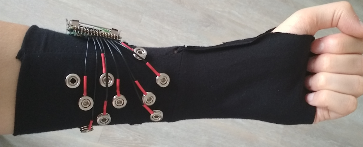
Cyber Wristband of Telepathy +2 [UNIQUE ITEM]
└2021-06-24, by Roman
Power Module 3 finally found a home: Sleeve 4. Looks a bit like a Pip-Boy from the Fallout Series :)

Under the hood there's 9 electrodes (1x ground, 8x signal):
New Frontpage + Logo
└2021-07-06, by Roman
The front page now looks a little more "modern", and I changed the logo from

to

Once again, this was inspired by the System Shock 2 Trioptimum logo.
Neurofeedback: Training in both directions
└2021-07-17, by Roman
For now, the training of neural networks mostly happens on the AI side. The
human makes arm gestures and presses keys on the keyboard. This provides the
input (electrode and
IMU signals) as well
as the output/labels (keyboard actions) to the artificial neural network, which then
learns the correlation between the two through
supervised gradient
descent.
Now I'm looking into how to train both the neural network of the AI as well as
the nervous system of the user through
neurofeedback, that is, by
making the user more aware of their neural signals, which in turn allows them
to fine-tune these.
My hope is that this will make up for the low quality of information that's
available to the AI, due to noise, attenuation, and the low number/quality of
electrodes. The user neither knows what signals the electrodes can access, nor
how to willingly produce movements that create these signals. Some gestures
work well, while others can't be detected at all, so the best bet is to use
forceful gestures with maximal muscle activation. But if there was some sort
of feedback to the user, like a visualization of the data that the neural
network is extracting, the user could focus on the movements that work, and
gradually lower the intensity, perhaps to the point where no actual movement is
required anymore.
Of course there is already some feedback about the signals: The PsyLink
UI shows the amplitude of each electrode in a rolling graph, and the
GNURadio application shows detailed plots of the raw signals, both of which
already help determining which movements will work for gestures and which will
not. But the AI can of course combine, cross-correlate, filter, convolve and
deconvolve the signals, which enables it to extract information that a human
won't see in the raw signal data.
Ultimately, the goal is that the user learns to, on demand, fire off just
enough neurons that PsyLink can pick up the signal and trigger the intended key
press without any visible movement of the arm.
Approach
As described above, simply presenting the user with the raw electrode data is
insufficient. A machine-learning approach will likely be optimal here, to
overcome the preconceptions of a top-down designer. Since we already have an
artificial neural network, why not use that one to generate the visualizations
too?
In my current version of this idea:
- The user needs to invent some arbitrary gesture that should correspond to
the action "Press key 'A'".
- The user is repeatedly asked to perform the gesture by the UI
- At random intervals
- For random durations
- With 2-3 seconds of heads-up warning to account for reaction time
- In between the gestures, the user should perform random other activities,
but never do the gesture without being asked by the UI
- The AI is trained on the fly with
- Electrode signals as input
- A binary label of "Key 'A' pressed" vs. "Key 'A' not pressed" as output
- Each data point is added randomly (80:20) to the training or validation dataset
- After X seconds of collecting data, the AI is trained for Y epochs
- Every Z milliseconds, the AI is asked to predict the output from the current
input, and the neural activations of the last non-output layer of the NN
are presented to the user visually, along with the predicted output.
- The visualization could be a heatmap or a scatterplot, for example
- The visualization should cover a large dynamic range (both small changes
and large changes to the values should be easily visible)
- Using the feedback, the user can tweak their gesture as desired, to e.g.
- Minimize the movement required to trigger the key
- Maximize the reliability with which the key press is predicted
- Over time, old data is dropped from the NN training to refine the
visualization and to keep the training time short.
Once the user is ready, they can add a second action like "Press key 'B'" and
so on.
Batch Update
└2021-11-30, by Roman
I haven't been posting recently because I've been focusing on other areas of my
life, but there has still been progress with PsyLink:
Prototype 6 improvements
I redesigned Power Module 3 to be more easily hand-solderable by enlarging the solder pads and adding thermal clearances to some of the filled copper areas. (The copper tracks to several pads were so wide that the heat of the solder iron was dissipating too fast into the copper, and the pads were not heating up properly). The result is Power Module 3.1.
Prototype 7
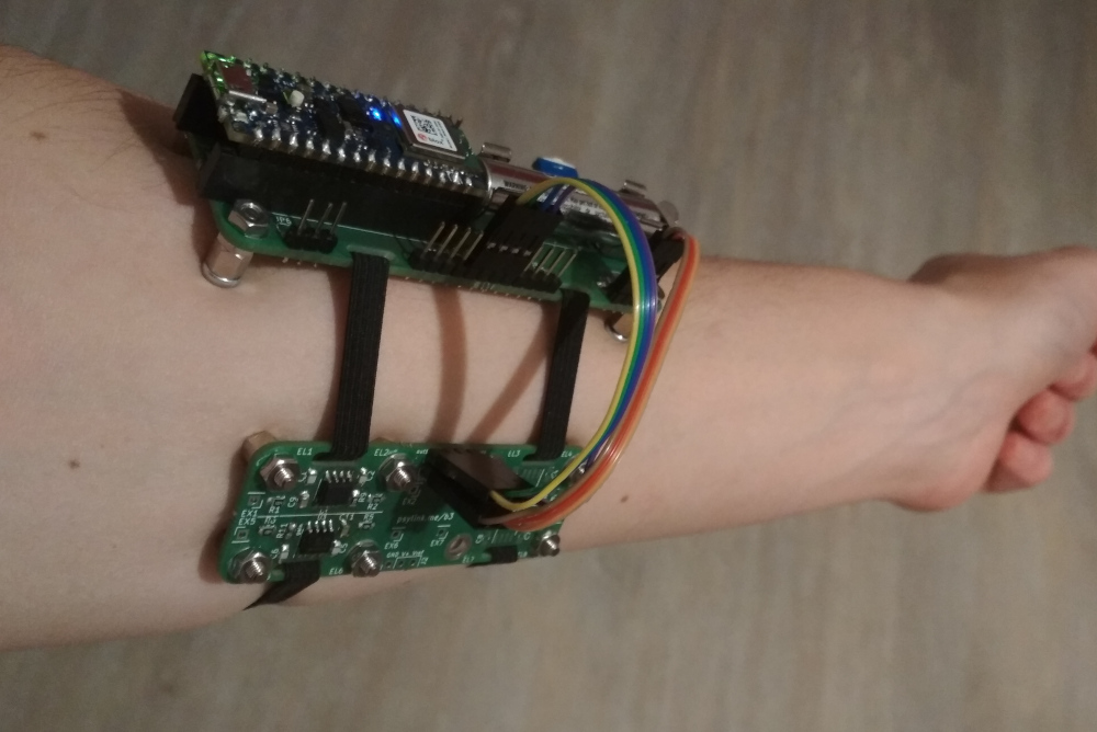
PerlinWarp reached out to me, and after some fruitful conversations, I build a Prototype 7 for him for research purposes. It's a hybrid of Prototype 4 and Prototype 6 which combines the advanced Power Module 3 with a cluster of Electrode Module 1 attached to Sleeve 3.
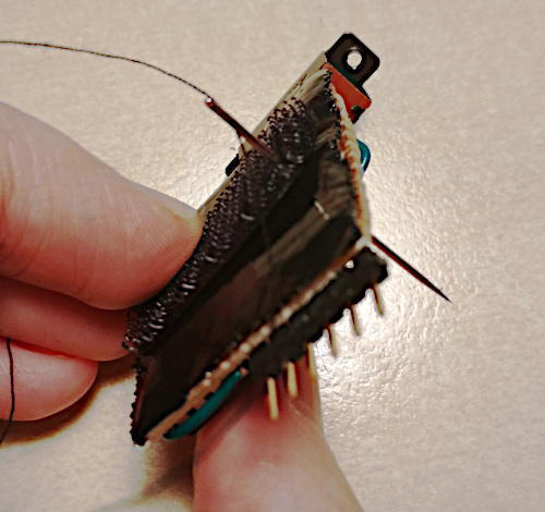
The assembly of the Prototype 7 took a full 20 hours of mindless labor,
so I had a LOT of time to think about improvements to the design that would
make it easier to assemble:
- Instead of having small boards for differential amplifiers that have to be
tediously connected with three fragile wires, bulk four of them up in a
single board.
- Instead of having a piece of custom-tailored fabric with precisely placed
electrodes, use electrodes made of metal screw-like parts that fit right
on to the PCB. The PCBs are held together with a rubber band that presses
the electrodes tightly to the skin.
- Made Power Module 3 more easily hand-solderable (described above)
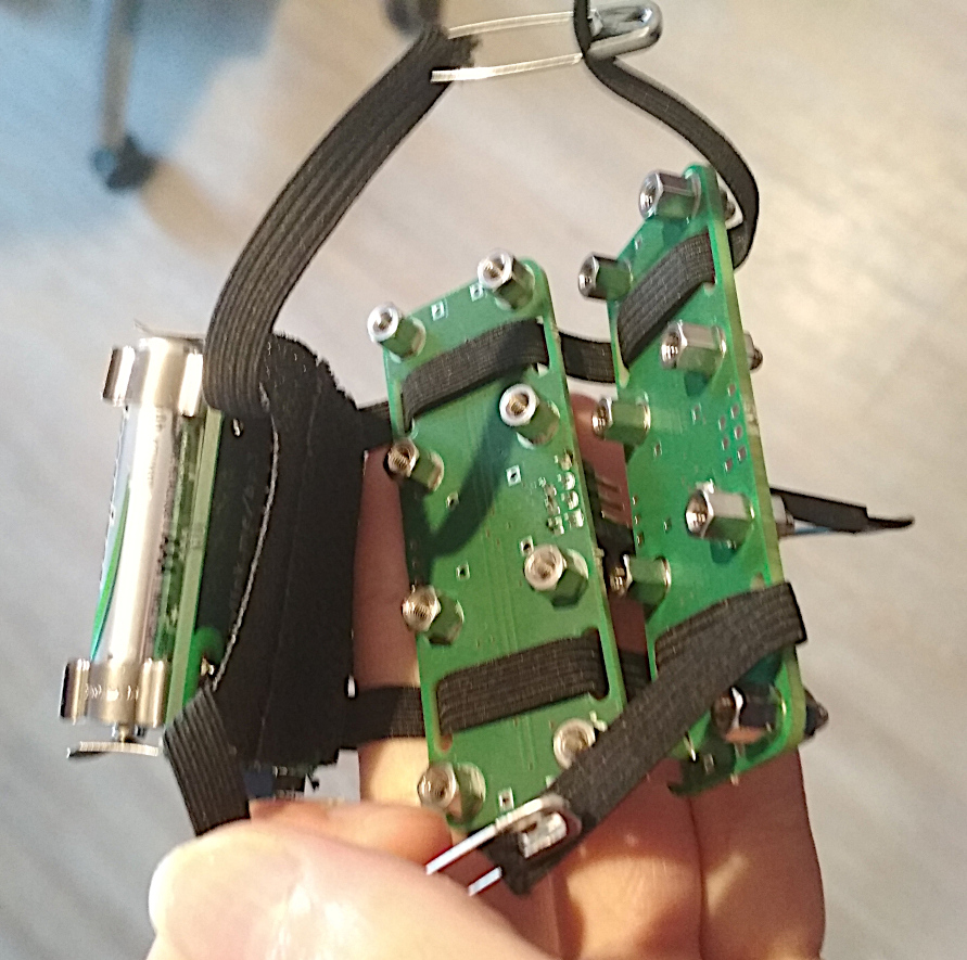
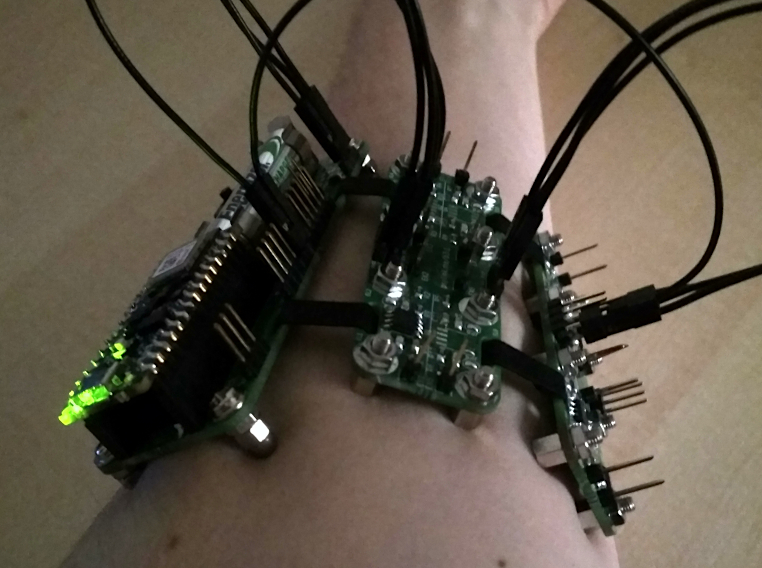
Prototype 8 (WIP)
The 8th prototype implements those changes, resulting in a device purely made
of PCBs connected by rubber bands and wires. These PCBs rest on the skin on
legs of metal, which double as the electrodes.
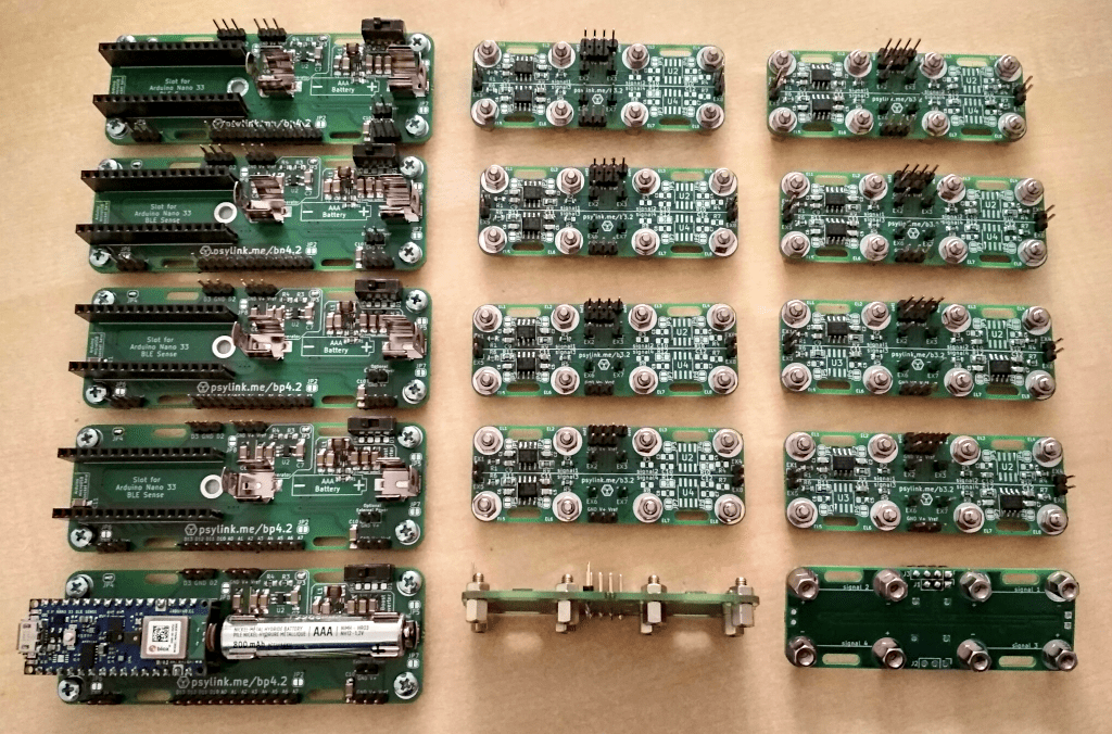
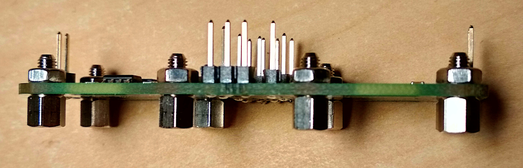
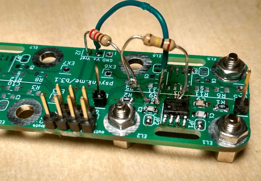
As of now, only the differential amplifiers are finished. The circuit for
these is Circuit 10 (electrodes):
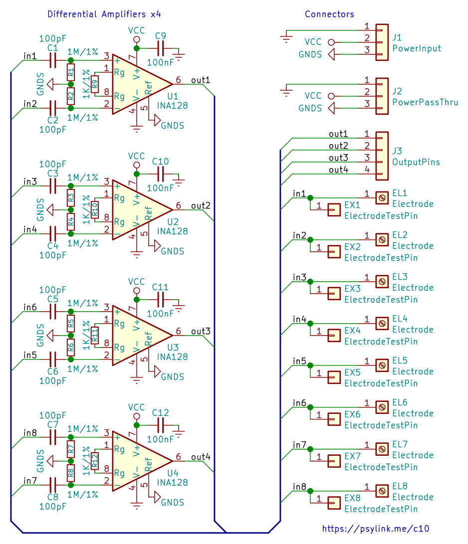
The front-side of the Electrode Module 3:
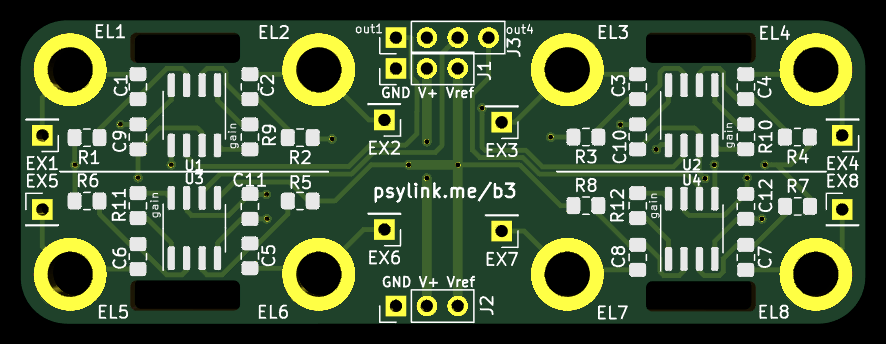
The four wide holes in the board are connection points for rubber bands, and
the eight round metal-plated holes are mounting points the electrodes. These
consist of a screw on one side, a nut on the other, holding both metal pieces
tightly in place.
The electrodes can be spacer screws like these or dome nuts like these. While the spacer screws seem to pick up a better signal, the dome nuts are considerably more comfortable thanks to the rounded cap, so I think I'll stick with these for now.
Dome nuts are also called "hutmutter" in German, which translates to "hut's
mother" (my nickname is hut), so just because of that fact, I had to try them
out.
Additionally, one can use the pins EX1 through EX8 to connect arbitrary
external electrodes.
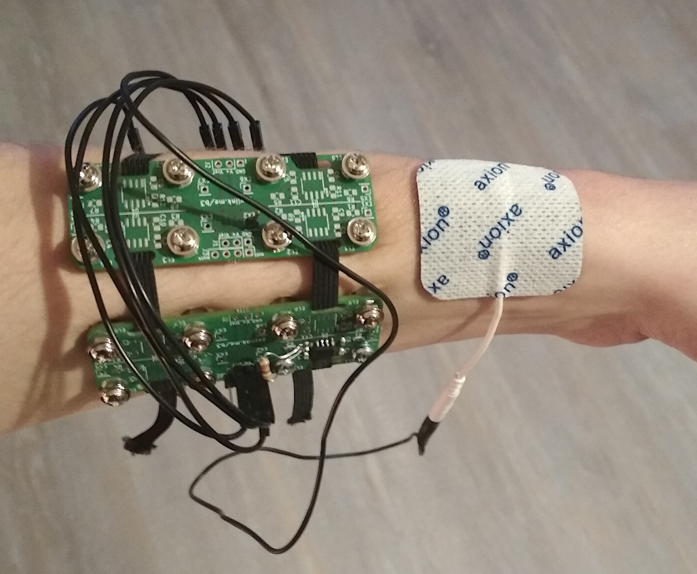
A first prototype using Electrode Module 3 and Power Module 3.1 (with an
improvised rubber band mounting mechanism) can be seen here:

I played around with using off-the-shelf wet EMS (electric muscle stimulation)
electrodes for the ground electrode, since good connectivity for the ground
electrode is important for a good signal.
I did not find an improvement in the signal though, perhaps wet electrodes are
not worth it.
Finally, the global microchip shortage has affected this project as well, and I could not find any sources for the power converter chips (TPS61220 DCKR) that boost the battery voltage of 1.2V to the required 5.0V. I still have some legit chips left, but in the long term, I need more of these, so I acquired some chips from Shenzhen via AliExpress. They have been advertised as "Original new, 100% quality", so what could POSSIBLY go wrong? But I tried them out, and they actually do their job quite nicely.
Future plans
The power module is currently only clumsily attached to the rubber band. The finished Prototype 8 will need a power module that's more compatible with the Electrode Module 3, by making it as long as the Electrode Module 3, and either by adding rubber band mounting holes, or by adding pin headers so that it can be stacked on top of the amplifier board, which would reduce the number of dangling wires as well.
I will also try out cheaper differential amplifiers to reduce the total cost of the device from ~70€ to ~30€ (excluding the ~39€ for the Arduino Nano 33 BLE Sense).
Power Module 4
└2021-12-15, by Roman
Prototype 8 needs a matching power module. I can't continue to awkwardly
stuff the rubber band between the velcro and the PCB of Power Module 3 like
this:

We need a PCB with proper rubber band holes and screw mounting points, so it
can be worn along the radius
bone
with about 2x Electrode Module 3 beside it.
Unfortunately the large dimensions of the Arduino and the battery make it a
little difficult. There's several options to do this, but none of them are
perfect:
- Place Arduino and battery beside each other like in Power Module 3
and either...
- make the board ~15mm longer to fit the holes.
- make the board ~12mm wider to fit the holes.
- Downside: It would be too wide to comfortably fit on the radius bone
- Downside of both options: it might feel unbalanced when worn on the side of the arm, because the heavy battery moves the center of mass off to the side
- Place Arduino and battery on top of each other, with pin sockets for the arduino that are taller than the battery, then make the board the size of Electrode Module 3 to fit the holes
- Downside: It might be hard to acquire pin sockets that tall
- Downside: Little space left for the holes and the remaining components, but might work
- Place Arduino and battery in a line next to each other and make the board 20mm longer and 8mm wider than Electrode Module 3 to fit the holes.
- Downside: The rubber bands are relatively close to the center, reducing the force with which the far ends of the board are pressed onto the skin
- Downside: The large dimensions might make it too bulky
- Remove the Arduino and solder the NINA-B306 bluetooth module of the Arduino onto the board directly, along with all the peripherals I need
- Downside: Unnecessary complexity
- Downside: More difficult soldering
- Instead of adding any holes, just stack the board on top of a Electrode Module 3 and use its screws and rubber band holes for physical support. (Thanks to PerlinWarp for that idea!)
- Downside: Would require a redesign of Electrode Module 3
- Downside: The height of the prototype might make it feel unbalanced
- Downside: The board would have be either wider or longer than the Electrode Module 3 due to the dimensions of the Arduino and battery. As a result, it would stick out to the sides, unless I enlarge the electrode board as well.
In the end I chose option 3 for simplicity reasons, and because the downsides
seemed the most acceptable. This also gives me a lot of space on the PCB which
is currently not needed, but may be used for analog multiplexing later on, to
allow supporting more than 8 electrodes.
I am quite tempted by option 2 though, it would make for a really compact
board. Maybe I give it a try later (if I ever find a source for 1x15 pin
sockets that are 14mm+ tall and 2.54mm spaced apart.)
Here is the resulting board. As you see, I also added a screw mounting hole in
the center, which should point right at the bone, which perhaps makes for a
great ground electrode. Any of the screws can be used as ground electrodes
though, simply by closing their respective solder jumper. I will try out
various combinations to see which one is best.
The matching circuit:

I ordered the production of this board already, and I'm excited to see if it
will work out like I imagine. :)
Fun story on the side: I ordered the boards on Aisler,
and they let you change the PCB design for free until it hits production. This
time, I had a couple of hours left, which I used to make a couple of
adjustments here and there, until I was happy and went to sleep. After 3 hours
I woke up, with racing thoughts, and I couldn't really fall asleep again (which
happens very rarely). After laying awake for 2 hours, it occurred to me that I
should run the automatic PCB layout check of KiCad once again to test my board
for obvious mistakes. Of course I had run the check before submitting my
order, and several times after doing my various modifications. But as it
turned out, I had indeed forgotten to run it on the final version, and there
were multiple errors too! Several unconnected nodes and some copper tracks
that were too close to each other. Luckily I caught this just a couple minutes
before my time for free modification ran out, and fixed it just in time.
Thanks insomnia.
INA155 Instrumentation Amplifier
└2021-12-16, by Roman
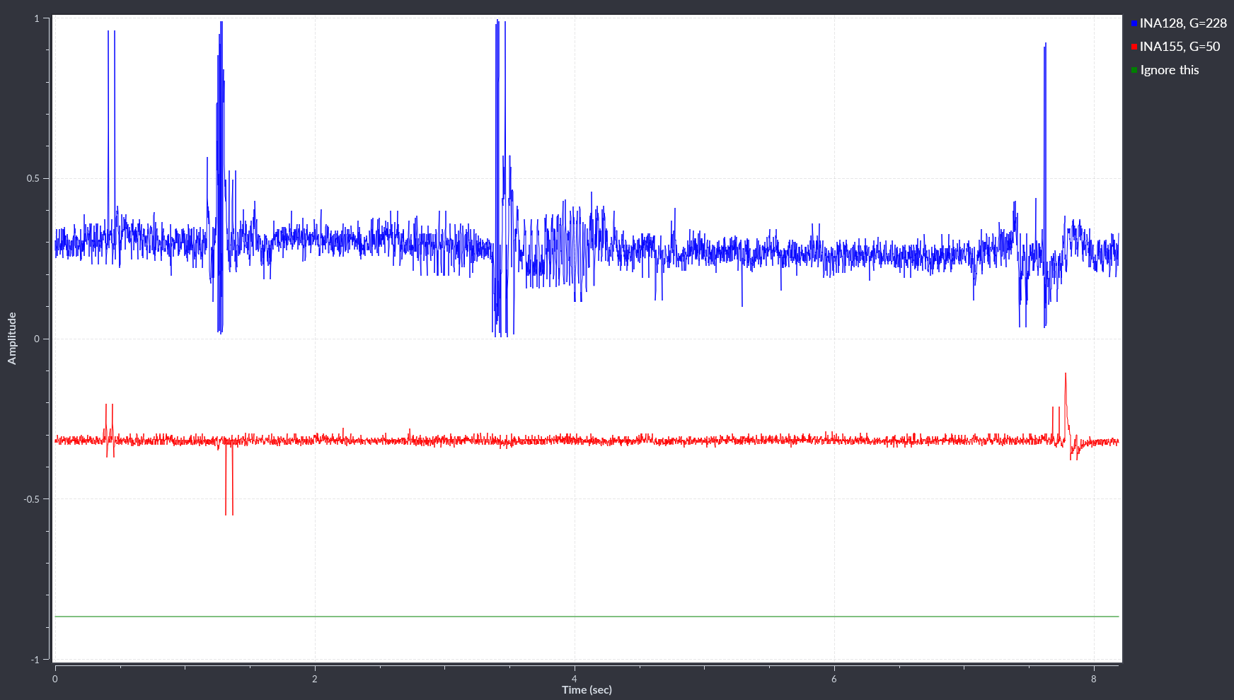
I tried replacing the INA128 chips on the
Electrode Module 3 with INA155 chips
with a Gain of 50, and it works just fine :) The signal even looks a little bit
cleaner than with the INA128, though I don't have good metrics to decide which
one is better overall. They both have the same PCB footprint so I didn't even
have to change the board design :)
This is good news. If I buy the INA155 chips in bulk (250+), they would cost
~1.75€ each (and I currently pay ~5.65€ per INA128), which would bring the
material cost of the whole product down from ~60€ to ~30€ plus
Arduino (~38€) plus shipment. Even if the INA155 is slightly worse, that's
totally worth it.
At this price, it would even be affordable to use more than 8 signals (with
additional analog multiplexing, since the Arduino only has 8 analog inputs)
and wear more than two Electrode Module 3 at the same time.
Another big plus is that INA155 chips can easily work with a supply voltage of
3.3V!! And I wouldn't need to boost the battery voltage all the way up to 5V
anymore, which is probably not very power efficient.
CORRECTION
I did some more tests and concluded that with the electrodes that I'm currently
using, the maximum gain of INA155 is not high enough, and I have to
either find better electrodes, add extra amplifiers, or switch back to INA128
for the time being. For now, the relatively expensive INA128s will have to do.
But hey, the current electrodes are literally just... plain metal spacer
screws, so there is DEFINITELY room for improvement.
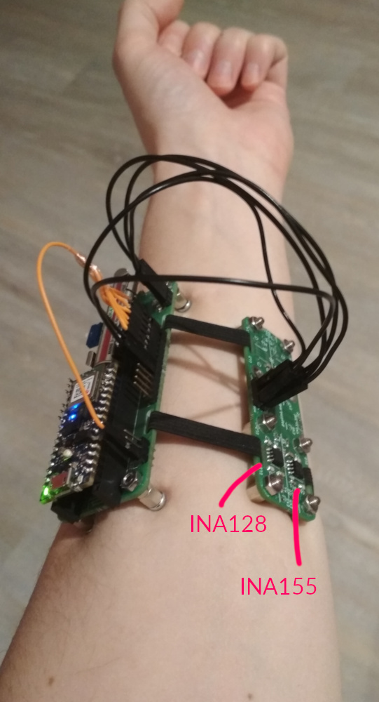
Here are some pictures of electrode placement and resulting signals, where you
can see that the INA128 (blue line) shows considerably more features:
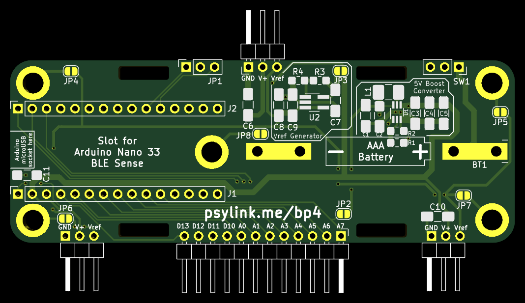
Prototype 8
└2021-12-18, by Roman
The order of the PCB of Power Module 4 has arrived, and so all the
parts for Prototype 8 are finally here :) After some assembly (and
crimping of some rainbow-colored connectors that look a little neater than
those stray black wires from previous photos), this is the final picture:
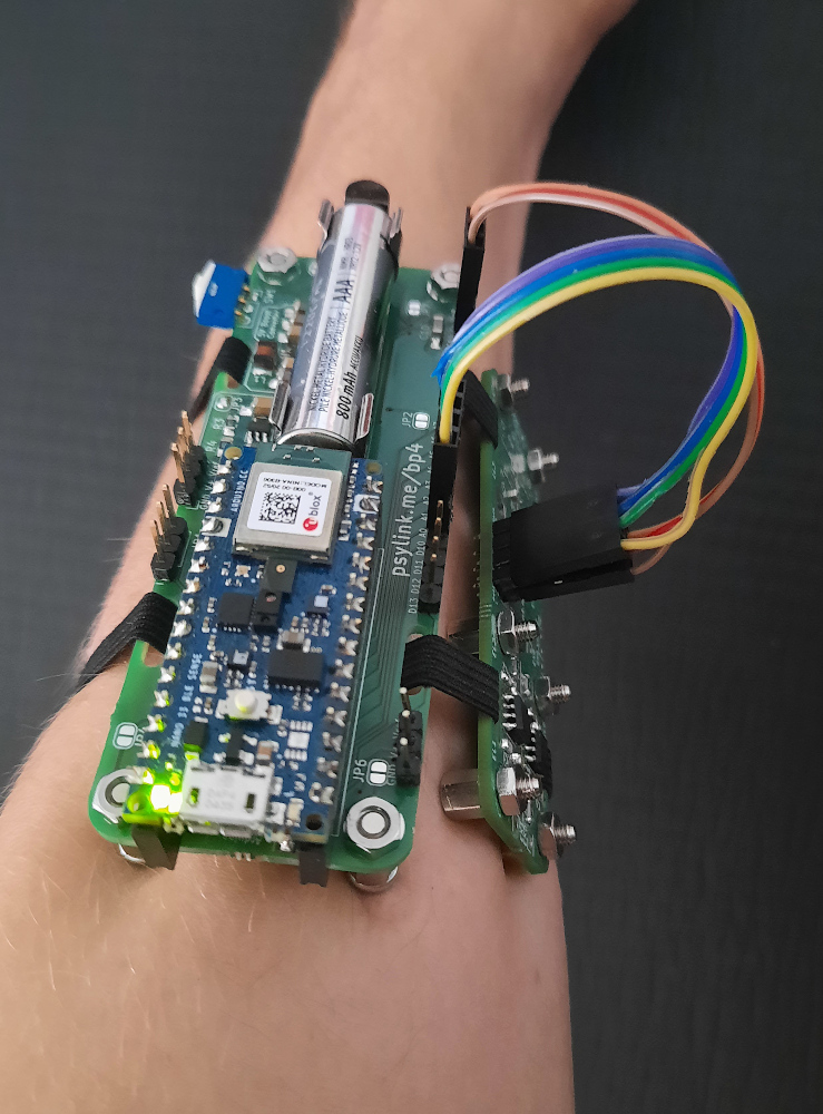
And another picture:
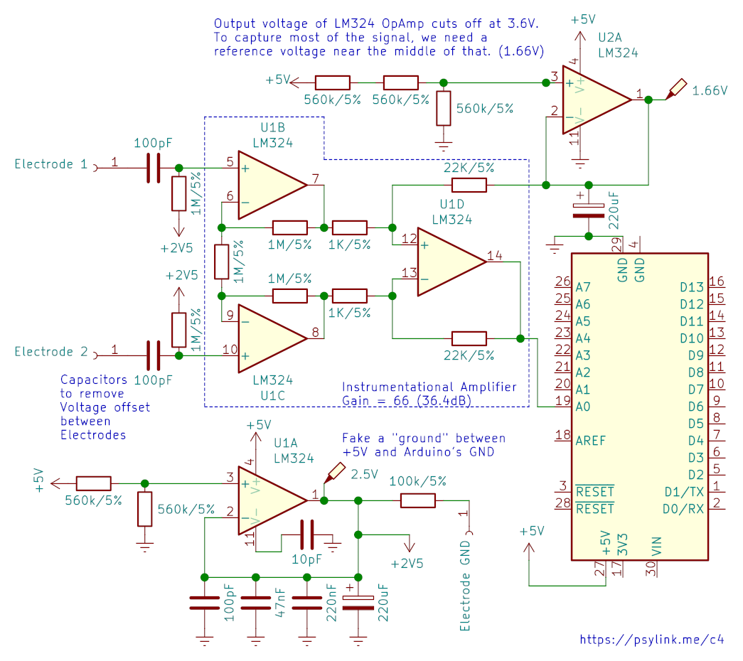
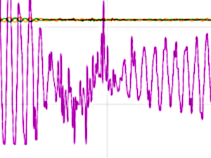
The Signal
A sample of the signal is this, using an INA128 with a gain of x228 and electrodes near the flexor digitorum superficialis:
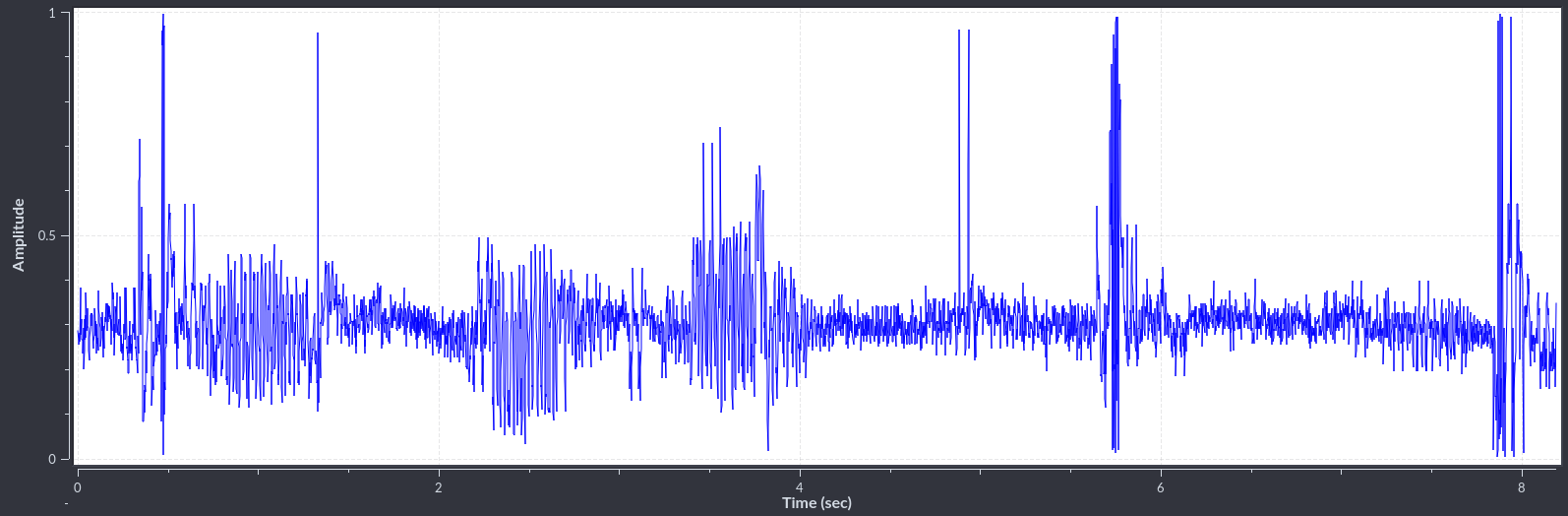
The baseline is the midly noisy line around a value of 0.3 and shows the state
of rest.
The spikes and "spindles" (periods of higher amplitude) occured when I
performed various movements, like extending the arm, snapping the fingers, or
twisting the wrist.
Bugs in the BP4
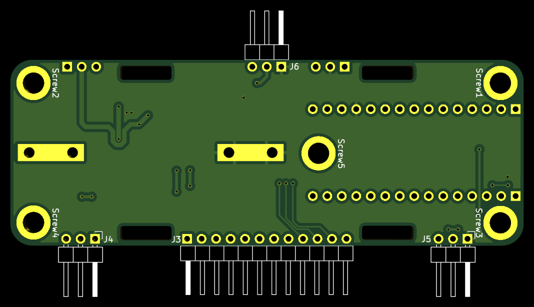
The Power Module 4 is not perfect though:
- The solder jumper J8, that activates the central Screw 5, overlaps with the
battery clip, resulting in a short circuit with the battery's ground, unless
I put some isolation tape over the jumper... Need to move the jumper further
away.
- The power switch (SW1) is too close to the Screw 2, so the switch I wanted to
use didn't actually fit, and I had to fall back to one that points off to the
side, and looks a little awkward.
- I also wish that the analog pins were closer to the power pins, so that I can
bundle up the wires, resulting in what would appear like one single
connector, rather than two, per Electrode Module 3. Although this may
lead to EM interference between the wires, reducing the quality of the
signal, so maybe it's actually better this way.
Prototype 8 Demo Video
└2021-12-19, by Roman
The demo video of Prototype 8 is out now:
HackChat & Hackaday Article
└2022-01-18, by Roman
Someone at Hackaday kindly invited me ("hut") to host a Hack Chat about
Electromyography and
PsyLink on
Wednesday, January 19, 8 PM GMT. There, I will answer all sorts of questions
from the hackaday community.
Drop by too, and watch me struggle for an hour to pretend that I know what I'm
talking about :)
Someone else at Hackaday also kindly wrote a whole article about
PsyLink,
which sparked nice discussions in the comments, got the P8 Demo
Video over 5k
views, and inspired several tinkerers to reach out to me about getting their
own PsyLink :)
Prototype 9 + Matrix Chatroom
└2022-01-19, by Roman
News #1: PsyLink now has a Matrix chatroom: #psylink:matrix.org
News #2: PsyLink Prototype 9 is now out, which is pretty much the same as Prototype 8,
just with a few bugfixes and enhancements. Notably:
- The Power switch now actually fits on the power module
- The Battery clip doesn't intersect with a solder jumper anymore, which used to cause a short-circuit unless you'd cover it up with tape
- The built-in electrodes on the electrode modules now can be activated/deactivated via solder jumpers, which allows you to use external electrodes while wearing the PsyLink regularily, without the built-in electrodes interfering with the signal.
Obligatory Picture:
It's less colorful and has more boards than the photo of the P8, but that's
just the type of wires, and an additional electrode module. You could make the
P8 look the same way.
Mass production
└2022-02-15, by Roman
More and more people are asking me to send them a PsyLink prototype! I've written some Tutorials to help the users to get started, and I'm working diligently to assemble them all. Can't wait to see the ways in which they will be used. :)
Request your own pre-assembled PsyLink now too!
Unlike software, unfortunately, you can't just download a PsyLink and use it
right away. It takes me about 1-1.5 hours per module to assemble these. I
wish I could automate and outsource more of the assembly process, but I don't
see a low hanging fruit worth exploring so far. Still, I'm happy about the
progress, since I'm now ~5x faster than when I sent out the first Prototype 7.
Currently, the assembly process consists of:
- File off the rough break-off points on the PCB to avoid scratching the skin
- Solder on the SMD components
- Do optical quality tests, as well as tests with a multimeter on critical parts
- Since my pin sockets have 16 pins and the Arduino has 15 pins, I cut off one of the pins of the socket
- Cut the downward-facing pins of all through-hole components down to ~1.4mm so that they don't stick out of the PCB and possibly scratch the skin
- Solder on the Through-hole components (except battery clips)
- Plug in the battery clips, bend its pins inward so that they don't scratch the skin, (the end may break off but that's ok), and solder them on
- Clean off solder flux stains with Isopropyl Alcohol on the sides that face the skin
- Cover the bottom of the power module with insulating tape to avoid skin contact
- Screw on the electrodes / legs
- Wire up everything as described in the wiki
- Push the elastic band through the respective holes to connect the boards together
- Do a test run of the entire system
Outsourcing pick&place and soldering of the components would be helpful, but
the through-hole components (pin headers/sockets, switch, battery clip) need
special treatment: I have to trim the pins so that they don't stick out of the
PCB and scratch the skin. I doubt that any pick&place contractor will do this
for me. This close-up shot of a Electrode Module 3.2 shows it well, that there
are no sharp points under the pin headers, just round solder blobs:
But I could at least outsource the soldering of SMD components. Let's see if I
can find something cheap.
If you have tips to accelerate the assembly process, please reach out to us.
Next Steps & Resources
└2022-02-16, by Roman
The PsyLink Wiki now contains two new pages:
- Next Steps documents potential directions that he project could take in the future
- Resources points to external pages that are connected to PsyLink, similar projects, related news, papers, and educational material.
If you have suggestions for potential next steps or know about interesting links, please let me know, or add them to the wiki. :)
Microchip 6N11-100
└2022-02-22, by Roman
In my quest for premature optimization, I tried out yet another instrumentation amplifier chip: The Microchip MCP6N11-100. At 1.55€, this chip is about 4 times cheaper than the INA128 instrumentational amplifier (which is currently the cost bottleneck), and would make a 16-electrode-PsyLink about half as expensive. It also works with as little as 1.8V (while INA128 requires 4.5V), eliminating the need for power conversion if a 3.7V lithium battery is used.
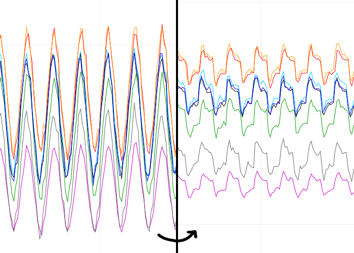
Unfortunately the pin configuration is different from the INA128 that the Electrode Module 3.1 normally uses, so I had to jury-rig the board a little:
But it worked, and the signal (the first one) is similar enough to those of INA128s (the last 4):
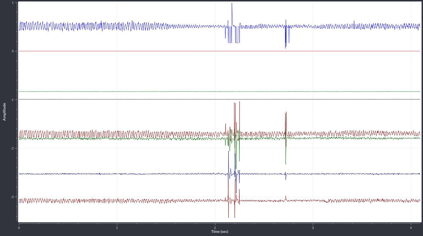
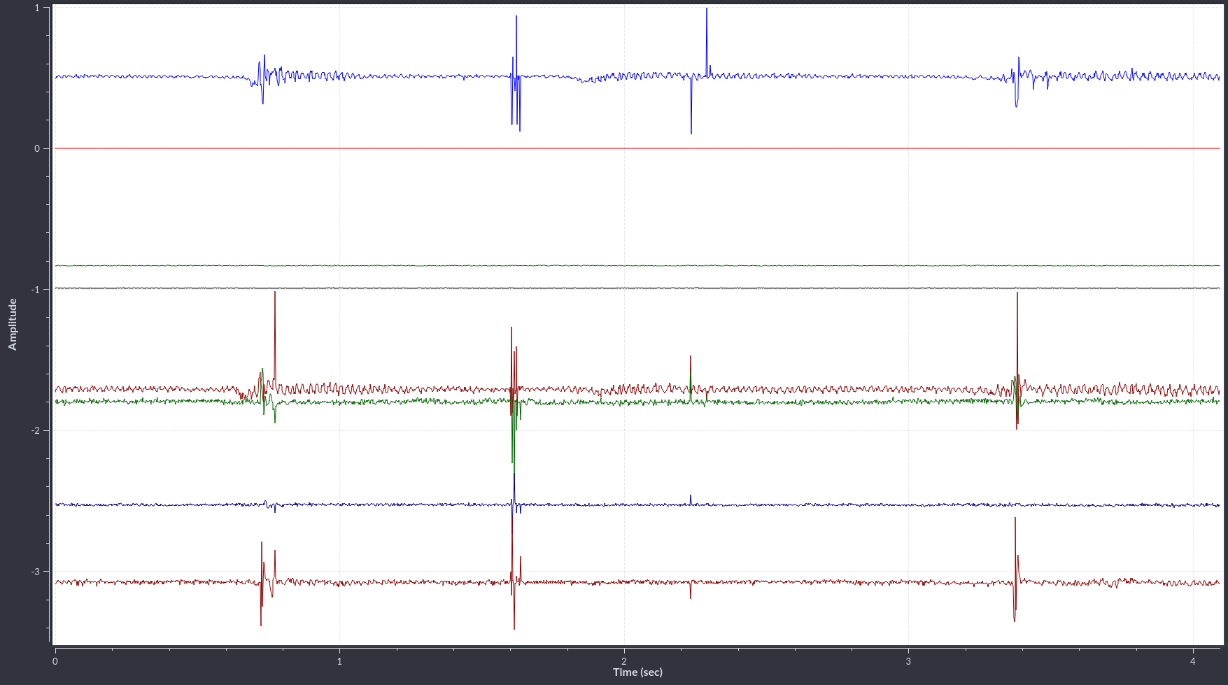
These were recorded with a Prototype 9.1 with two Electrode Module 3.1, one with 1x MCP6N11-100 at a gain of x501, and one with 4x INA128 with gains of x501 as well. I'm wearing it much like on the P8 demo video, except that there's two electrode modules side by side, not just one.
In the top center of the first picture (light blue signal), you can see that there is some clipping in the negative peaks of the wavelet, which is not great, but other than that, it does seem to show very similar signals. (They shouldn't be identical, of course, because each signal measures electrodes at different locations on the arm)
There's also a similar chip, the MCP6N16, which has a smaller footprint size and better performance, but has slightly higher cost and worse availability. It's more difficult to solder, too. But it's good to know that there's the option to switch to that one if we ever need to.
I'm quite happy with this result, and perhaps the next iteration of the electrode module will be designed for this chip rather than the INA128. :)
3M Red Dot electrodes
└2022-02-23, by Roman
Alex Lao suggested to try some 3M Red Dot electrodes, and so I got me some of the model 2248-50 (he actually suggested model 2660 but I mixed it up.) They are used for ECG patient monitoring, which is close enough, right?
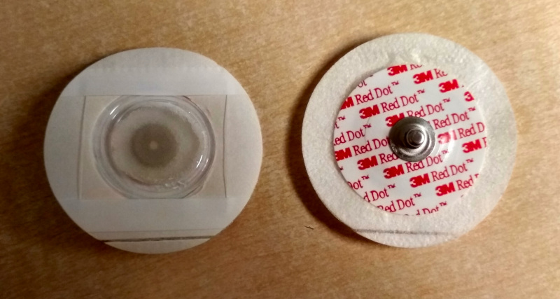
I connected two of them to EX1 and EX2 on an Electrode Module 3.1 and placed them on the flexor digitorum superficialis muscle (where I place the built-in PsyLink electrodes on most of the other pictures/videos too), and placed a third electrode on the radius bone near the wrist, and connected it to a Vref pin of a Power Module 4.2, which therefore acted as a ground electrode. The electrode module is the one from the previous blog post about the MCP6N11-100 instrumentational amplifier (for no good reason - I should have used INA128 for better comparability).
This is what they look like on my skin:
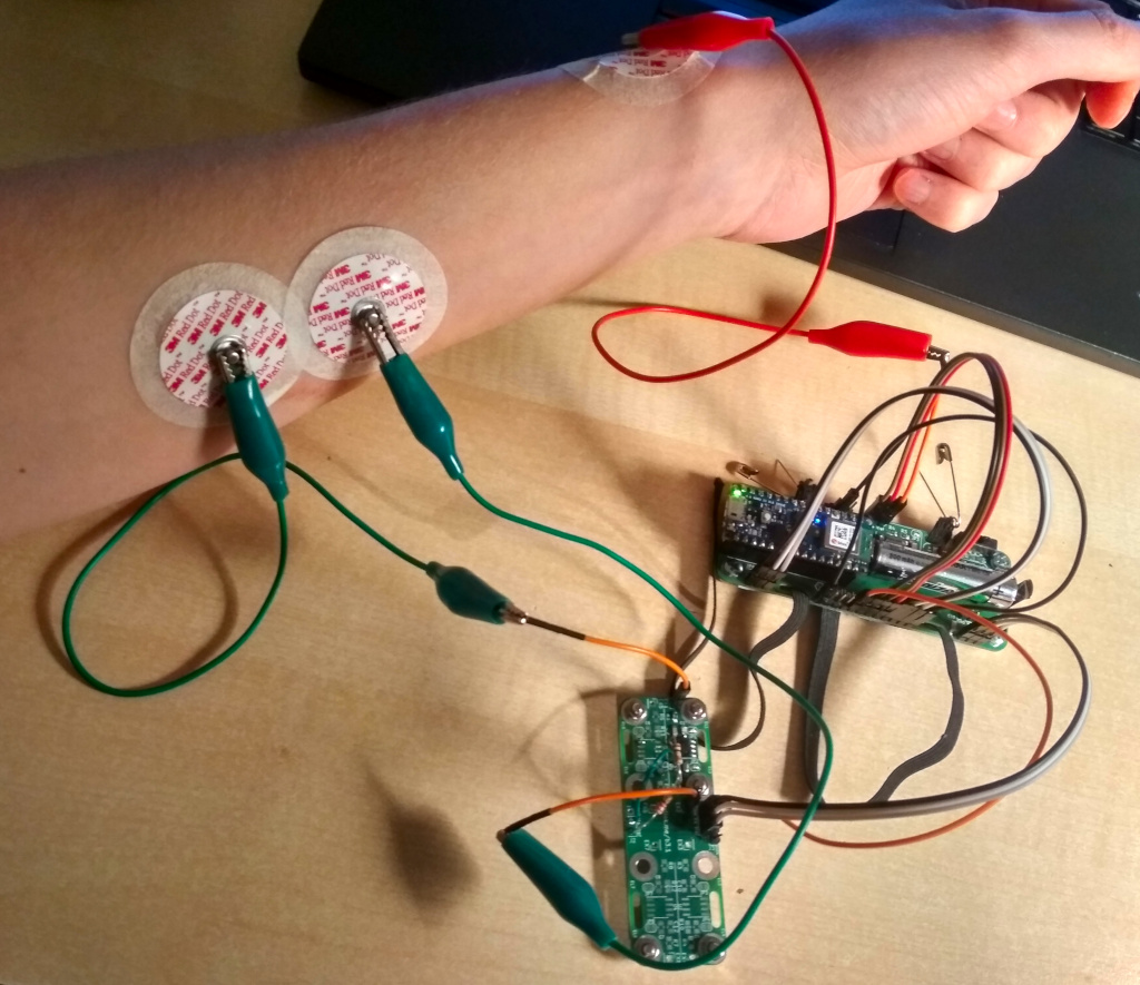
I recorded the following signals when pressing different fingers onto the table:
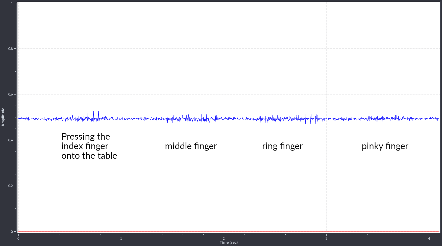
The amplitudes of the wavelets were a little disappointing, but perhaps boosting the gain from 501x to 1001x-2001x would help.
The nice surprise was the specificity of the signals. I only saw signals when I actually used that muscle. Unrelated movements like twisting the wrist sometimes produce strong signals with the built-in PsyLink electrodes, but produced no signal with these. There could be many reasons for that:
- The "unwanted" signals may be too weak to be visible against the noise
- There are less mechanical artifacts from electrodes moving around
- The ground electrode is closer to the wrist here, whereas in the default configuration, it's closer to the middle of the bone.
It's good to see that it works, and there's clearly a potential, but I'm not blown away either. Next steps could be:
- increasing the gain
- trying electrodes with better adhesion like the 3M 2660
Note that before attaching the electrodes, I did not shave off hair and did not clean off skin oils with alcohol, but at least I was fresh out the shower. Ok, time to end this post, this is getting weird :).
Added Bills of Materials
└2022-02-24, by Roman
This is long overdue, but the following prototypes now each have a BOM (bill of materials) in OpenDocument Spreadsheet (.ods) format, including a breakdown of the raw material cost, in case you'd like to replicate them:
2022 Retrospective
└2023-02-05, by Roman
I've gotten out of the flow of writing blog entries, but that doesn't mean we have been idle. There has been progress in the PsyLink sphere along various fronts and I could make several blog posts out of it, but I want to try something new, and summarize everything in a 2022 retrospective post:
Publicity
Early in 2022, Hackaday released an article on PsyLink (see HackChat & Hackaday Article) which pointed many eyes towards this project, and inspired several follow-up blog posts on other platforms:
PsyLinks into the Wild
Around 30 people have reached out to me following those blog posts, with their own stories, suggestions, and requests for collaborations, for which I am extremely grateful.
I could make arrangements for 8 people in 2022 to get their own PsyLink device for their personal research. (See also: Mass production) This is quite a small number, especially when compared to the spread of software-only projects, which anyone can obtain through a click of a download-button.
But let's look at the bright side: Instead of serving a large number of casual users, I served a smaller number of serious, enthusiastic users of which most have contributed back to the project. Thanks to all the new users for collaborating with me, it was a pleasure so far!
Yet, I'm looking into how to improve that number in the future, perhaps by outsourcing production or through cheaper components, faster assembly, and better advertising.
In total, there are now 9 PsyLinks in the wild: 4 in Europe, 4 in the USA, and 1 in Canada. That's 1x Prototype 4, 3x Prototype 9.1, 5x Prototype 9.2.
PsyLink P9.2
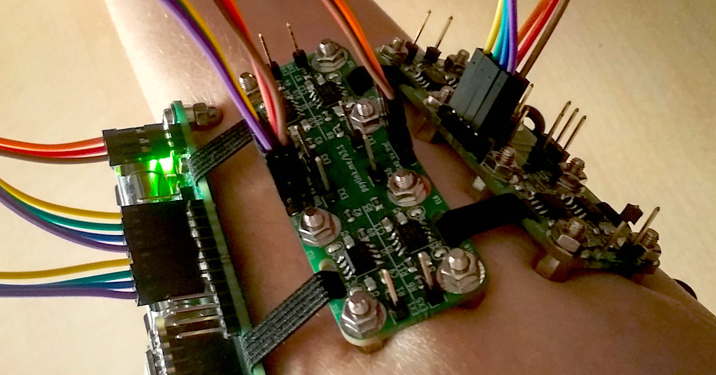
The design of the PsyLink Prototype 9.2 was finalized in early 2022, and has remained the standard prototype since then.
The modular setup of electrode modules allows custom-tailoring to specific purposes. The photo above shows a dense electrode layout (only 2 electrode modules with 8 electrodes each), but it's also feasible (although cumbersome) to go for an 8-electrode-module setup for maximum flexibility:

AntonX' Electrode Module for MCP6N11
The Microchip 6N11-100 seems quite promising for use in an electrode module, and AntonX designed a PCB that supports this chip natively:
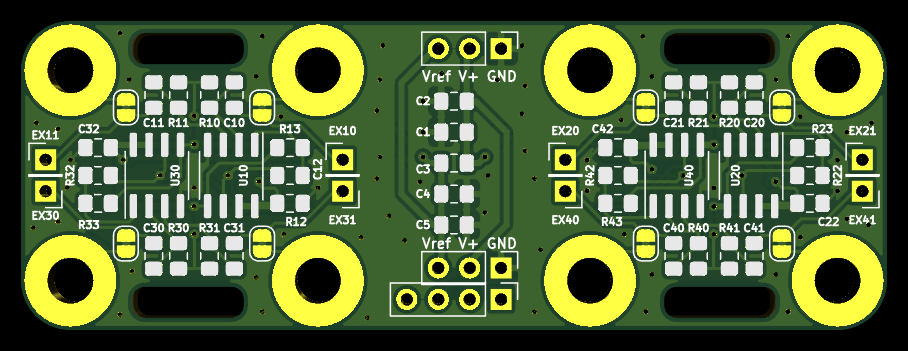
See also:
Thanks a lot to AntonX for designing this!
Hopefully I get to test out this board soon and evaluate how it compares to Electrode Module 3.2.
Before ordering it, I wanted to do some polishing: The connector for the signals (S1 through S4) should be at the top rather than bottom, like in Electrode Module 3.2, and the label with the link ("psylink.me/b4") should be on the front side rather than the back side, but that's relatively minor problems and maybe I should just go ahead and order it as it is.
3D-Printed Case
It's not a long-term solution to wear raw circuit boards on the skin. (Or is it?) John Shahbazian saw an opportunity, and designed a 3D-printed case for PsyLink's Power Module:
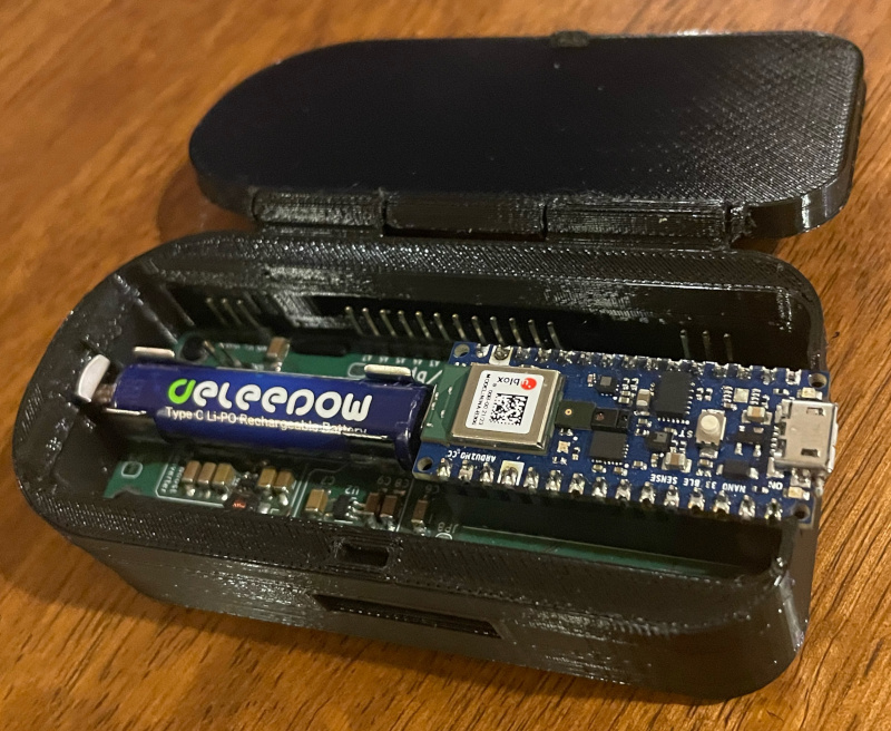
Thanks John for designing the case, this is a good start! I tried out printing it with the help of a friend successfully and it fits well, though we couldn't quite get the hinge to work.
What I would personally change:
- The hole on the side should rather be two holes, lined up with the holes on the power module PCB itself, so that the rubber band that holds the modules together can easily go through.
- Currently there's only one hole at the bottom, for one of the electrode screws. Since the user can choose which ground electrode they can use (and also for symmetry reasons), there should be 5 holes for all the electrode screws on the power module.
You can get the source files here:
PsyLink GUI for MacOS
John also built a convenient MacOS user interface for plotting PsyLink's EMG signals:
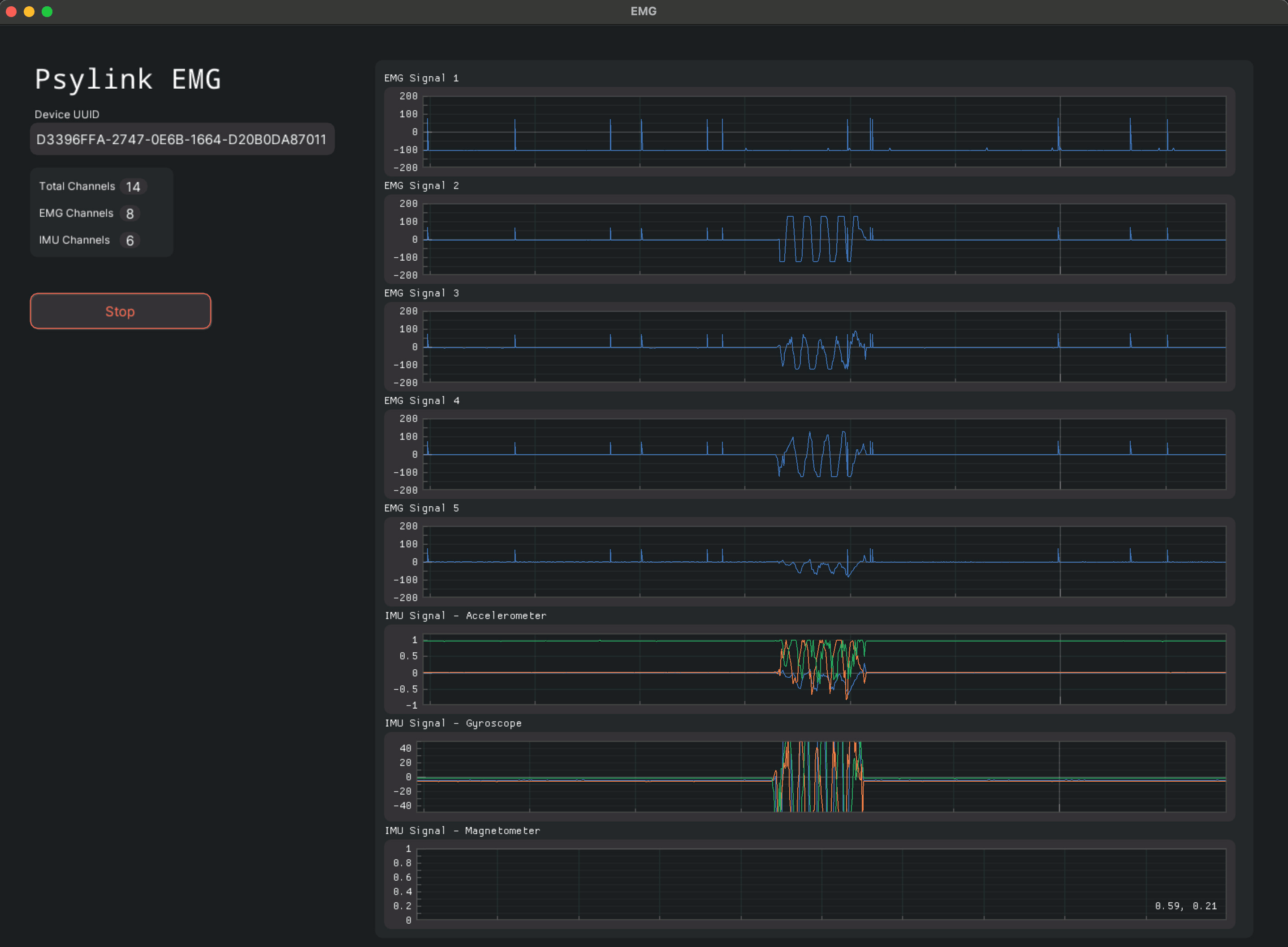
You can find his project PsylinkGUI.py on GitHub. Note that the software is not officially supported.
PsyLink as a Break-Out Board
PsyLink is mainly an EMG sensor, but can be turned into a wide variety of appliances. The power module, e.g. Power Module 4.2, can be used as a battery powered breakout board for the Arduino Nano 33 BLE Sense for any purpose besides neural interfacing.
For example, due to a domestic flooding situation, I wrote some quick-and-dirty code for water detection, plugged a PC speaker and 2 wires onto the PsyLink, and now it makes a siren sound whenever water touches the wires:

And of course PsyLink can also be used to power LEDs for a mobile, battery-powered mood light, see this mastodon post:
This is taking advantage of PsyLink's boost converter without using the Arduino at all:
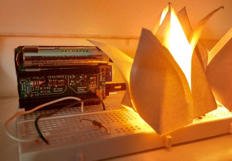
PCBWay has offered sponsorship for free PCB prototyping to the project, for which I'm very grateful. We haven't actually made any use of this sponsorship so far, but may do so in the future.
Finances
By the end of 2022, the project has cost me (Roman, the main author) about 2500€. (excluding lost income)
The total income from donations and PsyLink-related consulting work was about 1850€, which is more than I ever dreamed of earning from an open source project! Yet, it's not quite enough to cover the costs, and certianly not enough to pay my bills. (Not that making money was ever a priority of this project.)
As a result, I am currently looking for paid work as a freelance software developer, so that this project can stay independent and free. If you know of any company in the field of neural interfaces, medical devices or biotechnology that's looking for a freelancer to get some IT work done, let us get in touch!
What's Next
Hopefully the funding situation improves soon and I can dedicate more time to PsyLink and take on the next steps which are outlined in the wiki. :)
But of course there are now other PsyLink users out there and I am very excited what other contributions will come from the community.
Rochester Institute of Technology's Neurotech Exploration Team (NXT) is currently getting set up with their PsyLink and is looking into getting it to run on Microsoft Windows, and to control a 3D-printed robotic arm with PsyLink.
Good luck to everyone in the open source neural interface community, a big thank you to every PsyLink contributor, and a successful 2023 to you all! :)
Sample Signals
└2023-03-06, by Roman
On popular request, I have uploaded some data sets of recorded signals, along with videos of their recordings.
They can be found in the new git repository "psylink-datasets". Here's a quick overview:
Spelling Out "hello"
Here, I recorded 4 different gestures to produce 4 different keys, "h", "e", "l" and "o", obiously to be able to spell out the word "hello".
Unlabeled Samples
Here I perform various arm movements and simply display/record their signals.
Enhanced Signal by >1000%
└2023-03-22, by Roman
Through a very simple change in the circuit, we've been able to greatly enhance the EMG signal captured by PsyLink!
On the suggestion of Farzam, I took a closer look at the high-pass filter at the very beginning of the signal processing pipeline in Circuit 10.2 (electrodes) and it turns out that any signal under 1,600Hz is being weakened. This is a big problem, since the EMG signals that we are interested in are approx. 5-500Hz. By changing the capacitance from 100pF to 100nF, the cut-off frequency of the high-pass filter is shifted to 1.6Hz, leaving the EMG signal intact, while still removing low frequency noise and DC voltage.
The signal-to-noise ratio is through the roof. See for yourself:
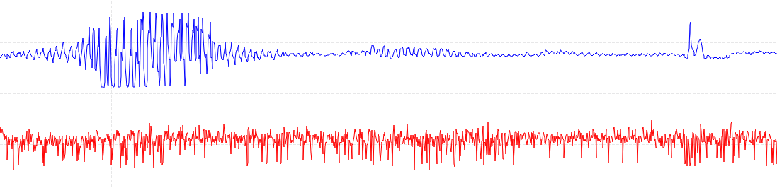
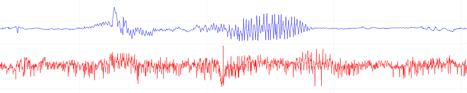
Red = before, Blue = after.
Some more details, if you're interested: These are two signals at out1 (blue) and out3 (red) on Circuit 10.2 (electrodes) where C1 and C2 have been changed from 100pF to 100nF while C5 and C6 have been left unchanged. The electrode pair of out1 is in a row and side-by-side to the electrode pair of out3 on the same muscle (flexor digitorum superficialis muscle, as usual), about 2cm apart, so they record almost the same information.
It's even more impressive if you consider that the red signal is 16x magnified in software. The red signal spans ~300mV whereas the blue one spans ~5V, making use of all the 12 bits of the Arduino's analog-to-digital converter (though the bluetooth connection currently transfers only 8 bits. To be fixed in the future.)
What I am especially excited about:
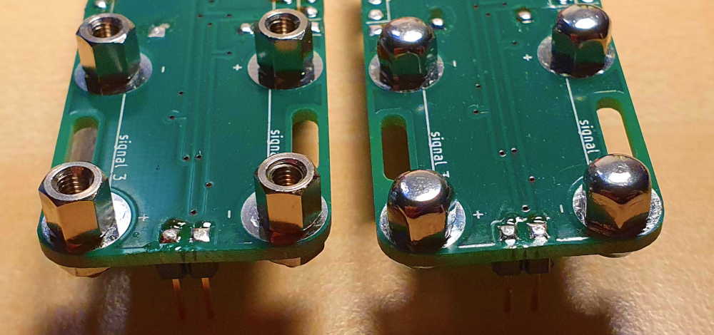
We can switch from the spacer screw electrodes (on the left) to the dome nut electrodes (on the right)! These are infinitely more comfortable, and mean that you can easily wear the PsyLink for hours.
The spacer screws bite into the skin and produce a better signal, but cause pain after a while. With this kind of ground-breaking improvement in signal quality, this trade-off is not worth it anymore and the dome nuts make more sense now.
In the coming days I will update the schematics to reflect these changes.
I highly recommend PsyLink users to swap their 100pF capacitors (C1-C8) for 100nF capacitors on their electrode modules. If you do not want to do this yourself, you will be pleased to hear that we are offering every existing PsyLink customer an upgrade free of charge. We will cover the material and delivery cost for you. Simply contact us if you're interested in the upgrade.
Prototype 10
└2023-05-31, by Roman
I'm excited to announce that we reached the double digits with Prototype 10! 🥳
As the most advanced prototype so far, it's more comfortable, more sensitive, and cheaper than any of the prototypes before (if we don't count the super-cheap early prototypes that don't use any amplifiers.)
The three big changes are:
- Enhanced Signal by >1000% by optimizing the passive high-pass filter before the amplifiers, as described in the previous blog post. See Circuit 10.4 (electrodes). (thanks Farzam!)
- Switched to cheaper Arduino Nano 33 BLE (without the extra sensors of the "Sense" model, which were actually not needed anyway)
- More comfortable rounded "dome nut" electrodes, as you can see on this photograph:

Along with this release, I have cleaned up the schematics folder in the git repository. and upgraded from KiCad 5 to 6. It should now be much easier for you to open/edit the PCBs/circuits. (Thanks AntonX!)
By the way, PCBWay kindly helped out by sponsoring their services, and I gave it a try and ordered pre-assembled PCBs. I never did that before, and of course, I made a bunch of mistakes with the order, but fortunately they quickly reached out to me, free of charge, and we fixed my mistakes before they went into production. I was very happy with the results and got exactly what I wanted on the first try. This kind of hand-holding sure takes off some pressure from experimenting with new technologies :) PCBWay also offers metalworking services, maybe it's finally time to dive into that and order some custom electrodes!
I hope you're also enjoying the continuous improvements I'm making to the website design, such as the rounded corners on the blog posts (only when more than one post is visible), the separator gaps between them.
Thanks to everyone who contributed ideas, code, financial support, and anything else to this project. For this release, it's especially Farzam Khodajoo and AntonX. We wouldn't have made it this far without you. Stay tuned for more updates! :)
Data Sheets
└2023-08-25, by Roman
After learning about the 4-document-model (permalink), an insightful guide to writing better documentation for software projects, I realized that PsyLink really suffers from having its documentation so spread-out among the dozens of pages with no clear reference page that contains it all.
As a first step to mitigate this, I wrote extensive data sheets for the power module and the electrode module, bundled right along with their source in the schematics folder. You can find them here:
Hopefully this will help you to get the most out of the boards and reduce the mistakes you do while replicating or using them!


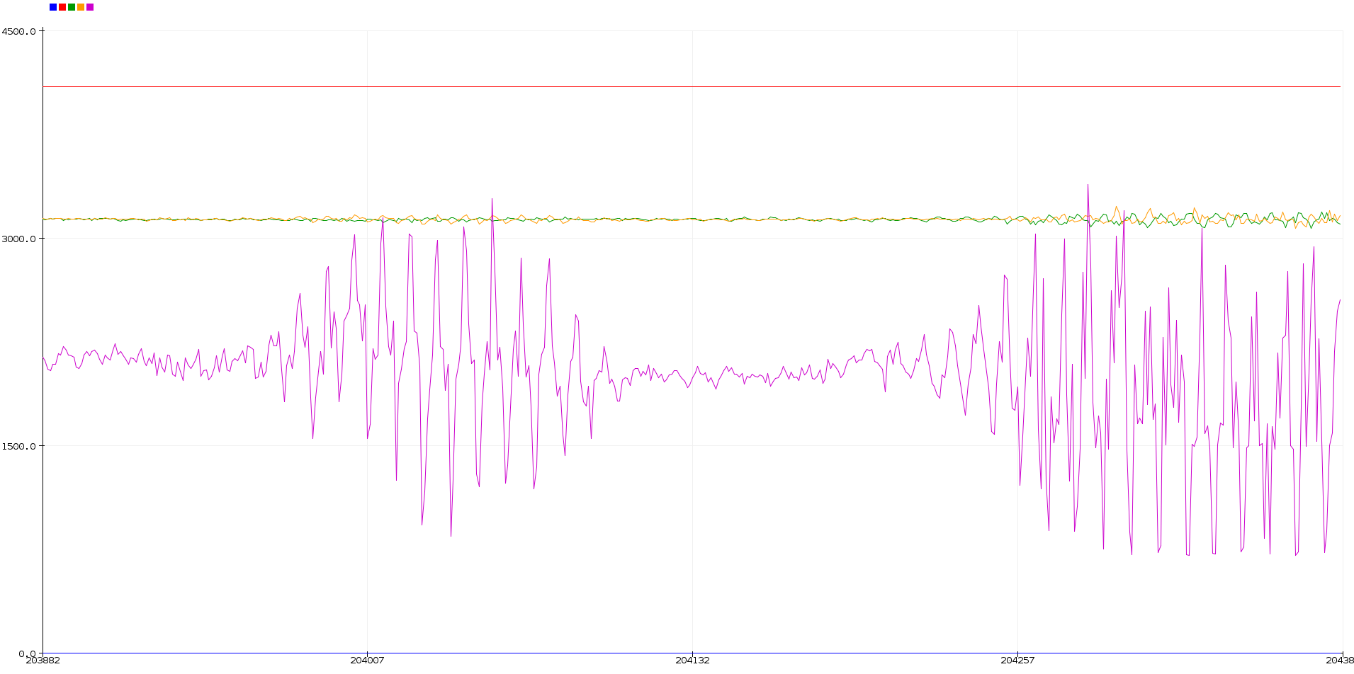


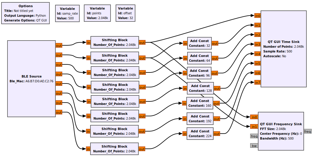
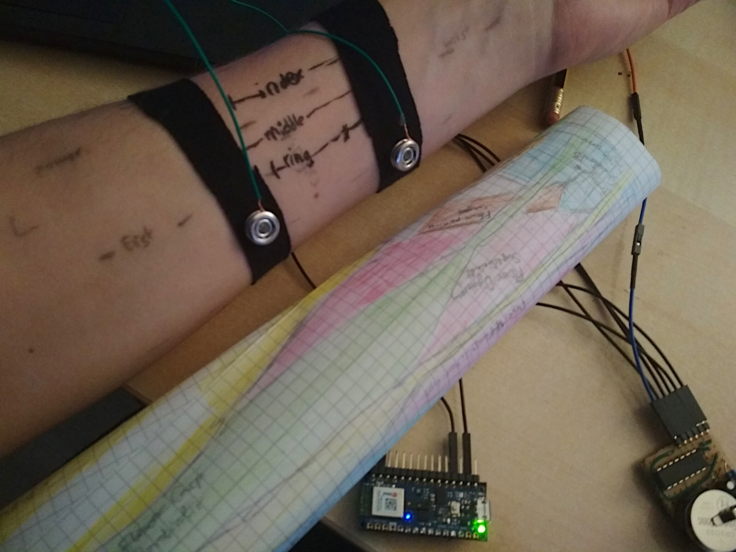
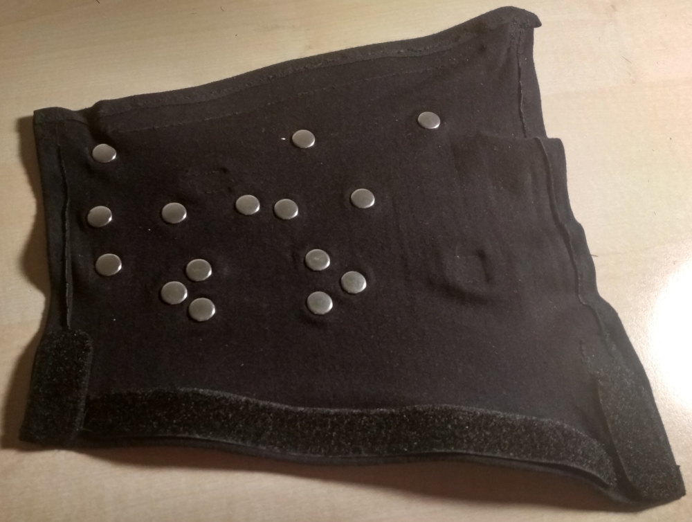
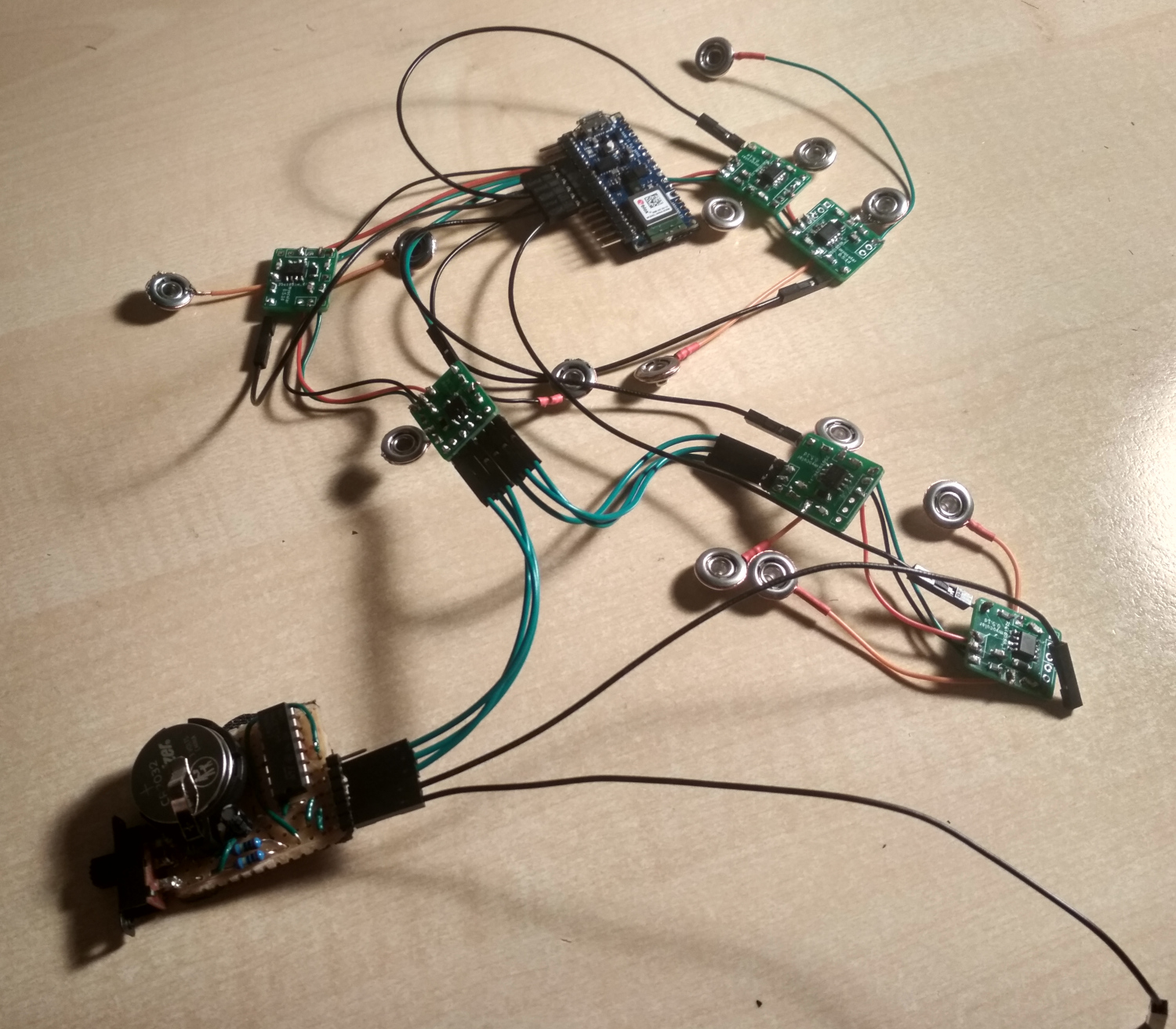
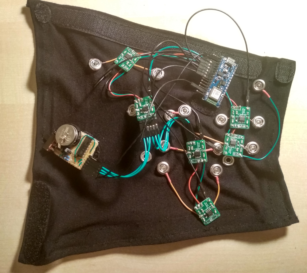

