Power Module 3
Since Power Module 2 has the wrong PCB layout for the step-up converter, I built Power Module 3 to fix this issue.
It was still a worthwhile learning experience to build Power Module 2, resulting in the following changes:
- Instead of stacking the Arduino and the Battery on top of each other (one on the front side of the board, one on the back), they're now side by side, to make the board flatter and fit better on the forearm.
- Added more capacitors all over the place
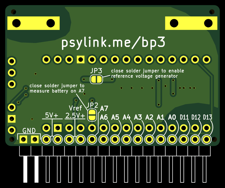
- Added various jumpers:
- A solder jumper to enable/disable the reference voltage generator, in case I come up with a setup where I won't actually need it
- A solder jumper to sacrifice one electrode and use its analog input pin to measure the battery charge instead.
- Three configuration pins, connectable via jumpers, to change software settings on the fly and toggle between up to 4 different modes. Or you can use them to plug in an extra module.
- Hopefully fixed the layout for the step-up converter
Here's the circuit:

And the new PCB:
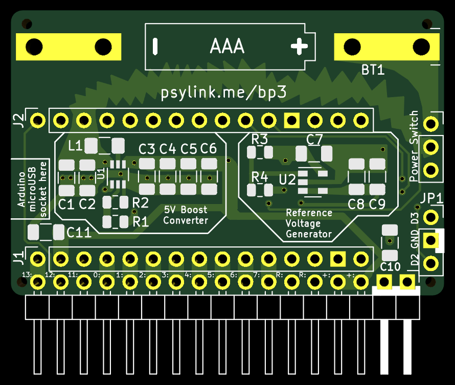
If you're wondering why the sparky, fancy looking power line goes all the way from the power switch on the right through digital pin D10 and into L1 on the left side... Indeed that looks pretty awkward, but L1 is the noisiest component, and I wanted to keep it as far as possible from the analog pins at the bottom, without sacrificing the effectiveness of the boost converter layout. Given the size & time constraints, I didn't find a better solution.
What time constraints, you ask? Well, actually I made a different PCB layout first. Polished every detail, and when it was perfect (according to my crude appraisal), I ordered it. Was already excited about the delivery, started putting the board on the website, and so on. But at some point I noticed that something was wrong... The Arduino pins were inverted. Theoretically, everything would still work, but the Arduino would have to be plugged in from the back side, which is something I wanted to avoid to keep the board laying nice and flat on the forearm...
Thankfully the manufacturing process hasn't started yet, and I could update the board for free. So I started redesigning half of the board and finished just in time for the production to start :D
Let's hope it works this time.
- Newer post: Running on AAA battery
- Older post: Believe The Datasheet
- All posts on a single page
- Date: 2021-06-16
- Author: Roman