Believe The Datasheet
Today the order of Power Module 2 arrived!
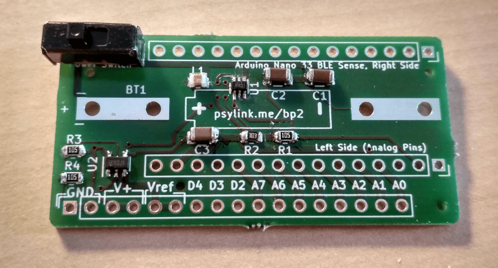
And with relief I saw that the battery clips fit nicely onto the board, as does the Arduino (with pin strips), and all the other components. Just that simple thing already felt like an accomplishment at my level of expertise with PCB design ;)
After some dreadful time trying to solder on the tiny 1x2mm-sized chip at U1 (I need a microscope for this shit), I had the SMD parts assembled and the circuit was ready for a test drive:
But something was weird. The output voltage was a meager 1.5V, not the expected 5V, even though everything was connected properly. After hours of debugging I flipped over the table and just soldered a fresh board, this time without the Vref-generating OpAmp (U2+R3+R4+C3). But no luck, still just 1.5V. This was lower than the minimal output voltage of the voltage booster, so the chip didn't even finish it's start-up phase. How could that be, if there's not even any load on the output voltage?
I desperately tried several different things. One was doubling the inductance at L1 from 4.7µH to 9.4µH by using two SMD inductances in series:
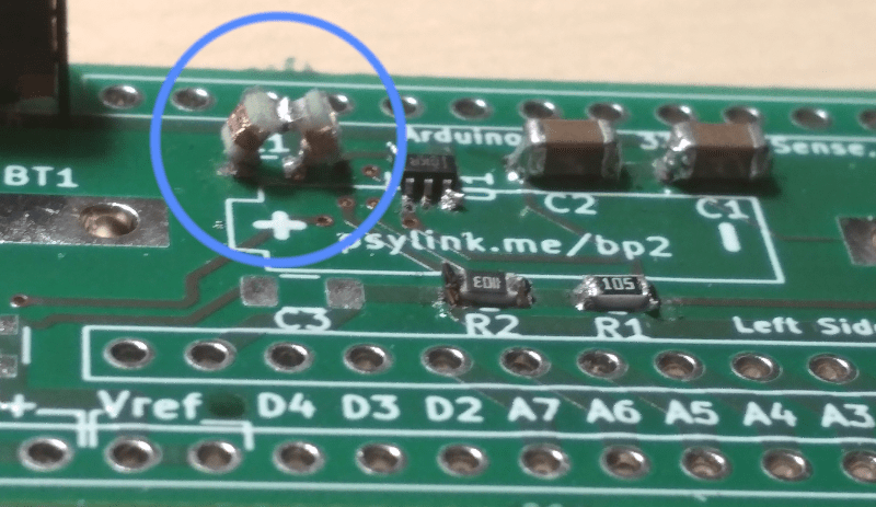
Unfortunately I think I broke the coils while constructing this, since they didn't let any current go through. But I found a regular, big inductance coil with 10µH, manually held its pins down onto the SMD pads, and indeed, the voltage jumped up to 5V!
So I soldered it... onto... the SMD pads.

(Probably you can reconstruct my entire room from all the reflections in this image, along with a biometric picture of my face and at least 3 of my fingerprints...)
But once I connected the OpAmp, the voltage went back down to 2.5V, and with the Arduino connected, it went down further to 2.4V. Adding a second coil in series for a total of 20µH didn't compensate for this, but made it even worse, bringing it all the way down to 1.5V.
Well, clearly whatever is wrong with this construction has something to do with the inductance, and it's not purely the amount of inductance... Which brings us to the title of this post:
The mistake (probably)
Of course the data sheet of the voltage booster CLEARLY STATED that the inductance coil needs to be AS CLOSE AS PHYSICALLY POSSIBLE to the chip. The capacitors C1 and C2 too, by the way. And I even read that. But I thought, what could possibly go wrong if I move it ~1cm away to make some space for the battery? Nothing, right? Well, awesome, I guess it's time for another revision :)
At least the 2.4V were enough to power the Arduino, although it was visibly struggling. I could establish a Bluetooth connection and collect some signals, but the Bluetooth packets were coming in extremely slowly (though still faster than mobile internet in 80% of Germany.)
Pictures
Front:
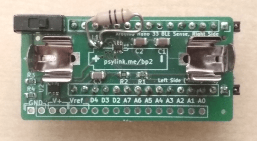
Somehow the oversized inductance coil adds a nice vibe to it.
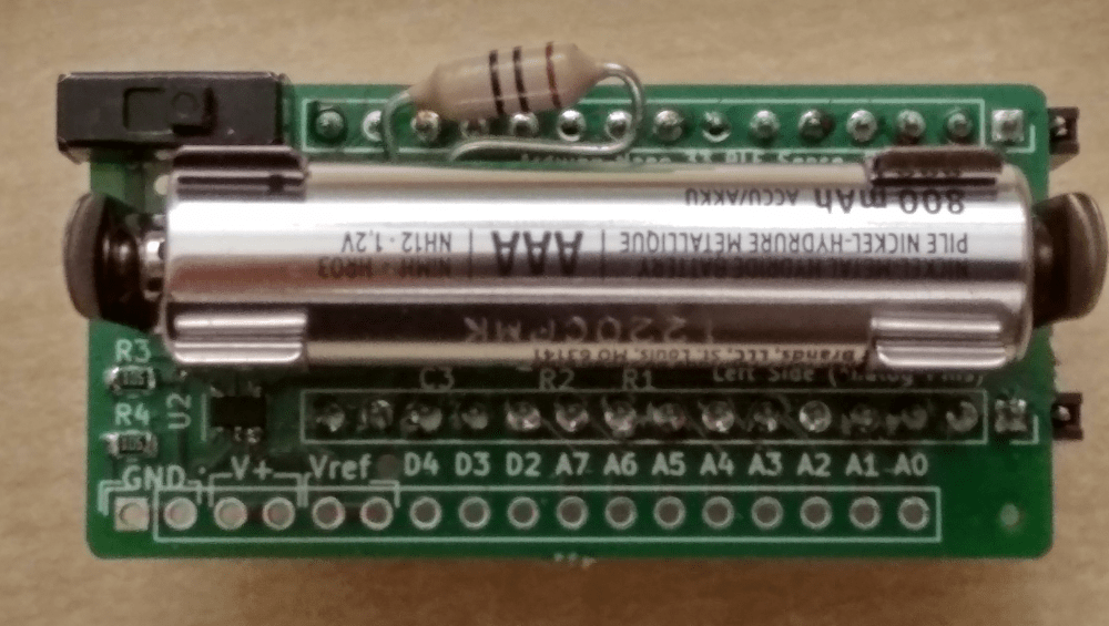
Front, with battery:
Back, with attached Arduino:
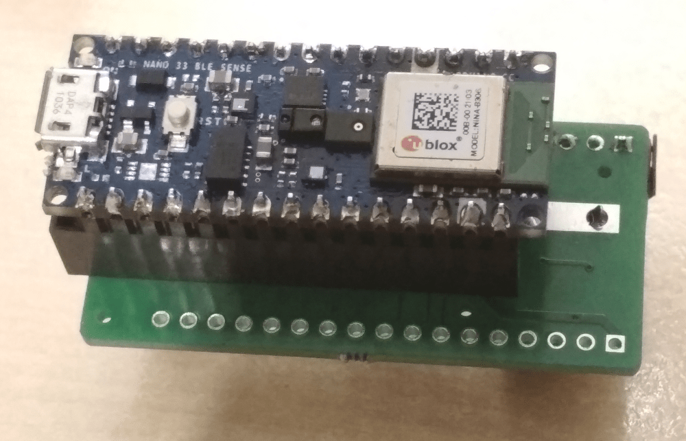
This picture shows a pin strip socket that will be gone in the final version, where the Arduino will be soldered onto the board, reducing the height from 3cm to 2cm.
Side, with Arduino and battery:

(Yes, the pin strip socket is too long by one pin ;))
- Newer post: Power Module 3
- Older post: Back to the Roots
- All posts on a single page
- Date: 2021-06-10
- Author: Roman