PsyLink is experimental hardware for reading muscle signals and using them to e.g. control the computer, recognize gestures, play video games, or simulate a keyboard. PsyLink is open source, sEMG-based, neural-network-powered, and can be obtained here.
This blog details the steps of building it and shows recent developments. Subscribe to new posts with any RSS reader, and join the community on the Matrix chatroom.
- All posts on one page
-
2025-05-01: PsyLink Talk
-
2024-08-16: Mass Production #2
-
2024-08-01: Android: First Step
-
2024-07-25: Rev2 Firmware
-
2024-07-24: Prototype Fund
-
2023-08-25: Data Sheets
-
2023-05-31: Prototype 10
-
2023-03-22: Enhanced Signal by >1000%
-
2023-03-06: Sample Signals
-
2023-02-05: 2022 Retrospective
-
2022-02-24: Added Bills of Materials
-
2022-02-23: 3M Red Dot electrodes
-
2022-02-22: Microchip 6N11-100
-
2022-02-16: Next Steps & Resources
-
2022-02-15: Mass production
-
2022-01-19: Prototype 9 + Matrix Chatroom
-
2022-01-18: HackChat & Hackaday Article
-
2021-12-19: Prototype 8 Demo Video
-
2021-12-18: Prototype 8
-
2021-12-16: INA155 Instrumentation …
-
2021-12-15: Power Module 4
-
2021-11-30: Batch Update
-
2021-07-17: Neurofeedback: Training in …
-
2021-07-06: New Frontpage + Logo
-
2021-06-24: Cyber Wristband of Telepathy …
-
2021-06-21: Running on AAA battery
-
2021-06-16: Power Module 3
-
2021-06-10: Believe The Datasheet
-
2021-06-04: Back to the Roots
-
2021-05-31: Website is Ready
-
2021-05-29: Dedicated Website
-
2021-05-17: Gyroscope + Accelerometer
-
2021-05-14: Wireless Prototype
-
2021-05-09: Power Supply Module
-
2021-05-07: New Name
-
2021-05-06: Finished new UI
-
2021-05-04: Higher Bandwidth, new UI
-
2021-04-30: PCB Time
-
2021-04-29: Soldering the Processing Units
-
2021-04-28: Going Wireless
-
2021-04-24: First Amplifier Circuit
-
2021-04-19: Amplifiers
-
2021-04-15: Multiplexers
-
2021-04-14: Data Cleaning
-
2021-04-13: Cyber Gauntlet +1
-
2021-04-11: Adding some AI
-
2021-04-09: F-Zero
-
2021-04-08: Baby Steps
-
2021-04-03: The Idea
Added Bills of Materials
└2022-02-24, by RomanThis is long overdue, but the following prototypes now each have a BOM (bill of materials) in OpenDocument Spreadsheet (.ods) format, including a breakdown of the raw material cost, in case you'd like to replicate them:
3M Red Dot electrodes
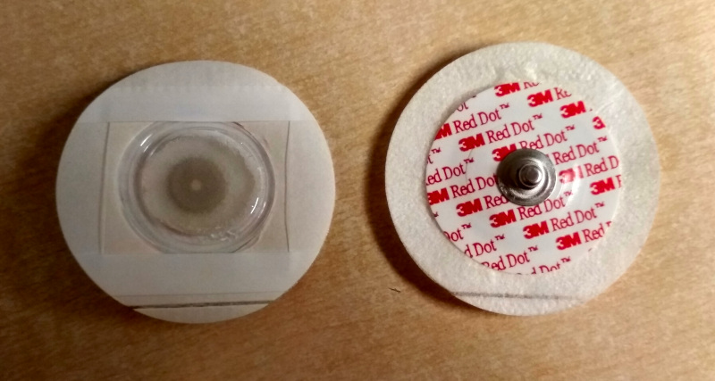
└2022-02-23, by RomanAlex Lao suggested to try some 3M Red Dot electrodes, and so I got me some of the model 2248-50 (he actually suggested model 2660 but I mixed it up.) They are used for ECG patient monitoring, which is close enough, right?
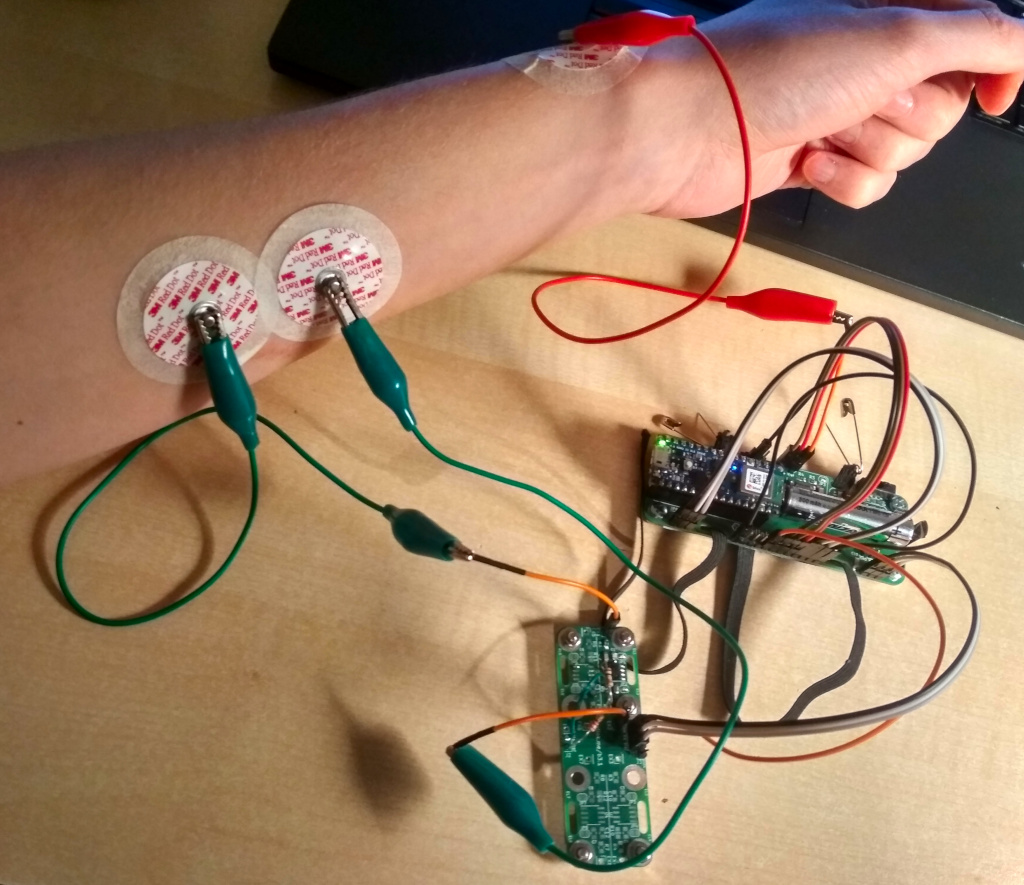
I connected two of them to EX1 and EX2 on an Electrode Module 3.1 and placed them on the flexor digitorum superficialis muscle (where I place the built-in PsyLink electrodes on most of the other pictures/videos too), and placed a third electrode on the radius bone near the wrist, and connected it to a Vref pin of a , which therefore acted as a ground electrode. The electrode module is the one from the previous blog post about the MCP6N11-100 instrumentational amplifier (for no good reason - I should have used INA128 for better comparability).
This is what they look like on my skin:
I recorded the following signals when pressing different fingers onto the table:
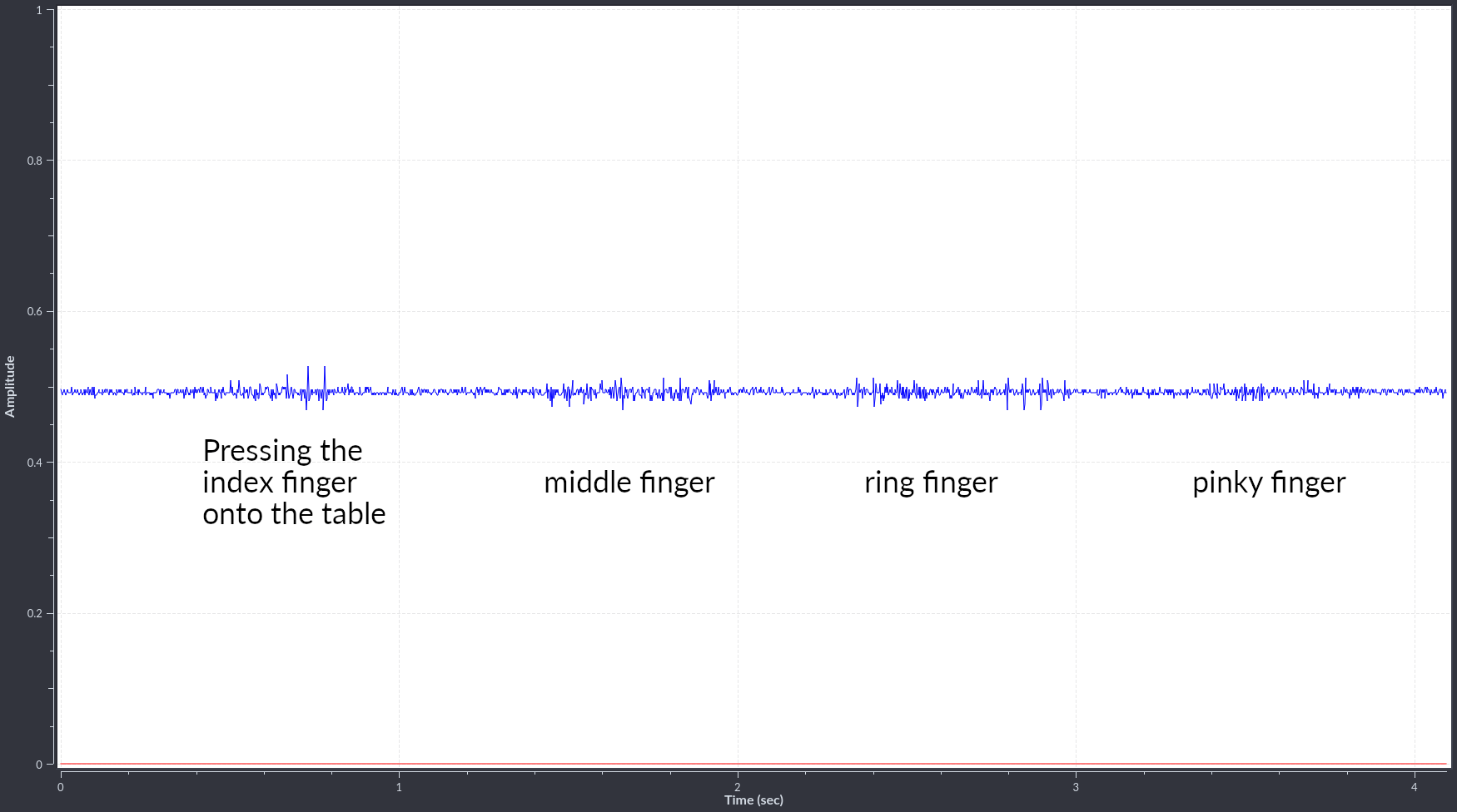
The amplitudes of the wavelets were a little disappointing, but perhaps boosting the gain from 501x to 1001x-2001x would help.
The nice surprise was the specificity of the signals. I only saw signals when I actually used that muscle. Unrelated movements like twisting the wrist sometimes produce strong signals with the built-in PsyLink electrodes, but produced no signal with these. There could be many reasons for that:
- The "unwanted" signals may be too weak to be visible against the noise
- There are less mechanical artifacts from electrodes moving around
- The ground electrode is closer to the wrist here, whereas in the default configuration, it's closer to the middle of the bone.
It's good to see that it works, and there's clearly a potential, but I'm not blown away either. Next steps could be:
- increasing the gain
- trying electrodes with better adhesion like the 3M 2660
Note that before attaching the electrodes, I did not shave off hair and did not clean off skin oils with alcohol, but at least I was fresh out the shower. Ok, time to end this post, this is getting weird :).
Microchip 6N11-100
└2022-02-22, by RomanIn my quest for premature optimization, I tried out yet another instrumentation amplifier chip: The Microchip MCP6N11-100. At 1.55€, this chip is about 4 times cheaper than the INA128 instrumentational amplifier (which is currently the cost bottleneck), and would make a 16-electrode-PsyLink about half as expensive. It also works with as little as 1.8V (while INA128 requires 4.5V), eliminating the need for power conversion if a 3.7V lithium battery is used.
Unfortunately the pin configuration is different from the INA128 that the Electrode Module 3.1 normally uses, so I had to jury-rig the board a little:
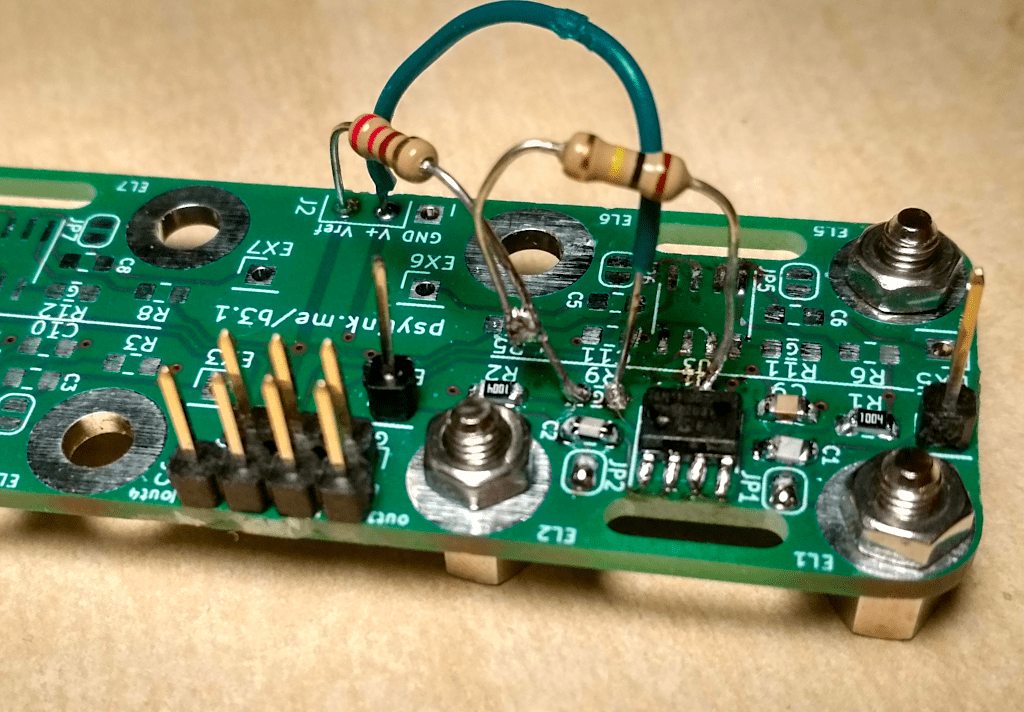
But it worked, and the signal (the first one) is similar enough to those of INA128s (the last 4):
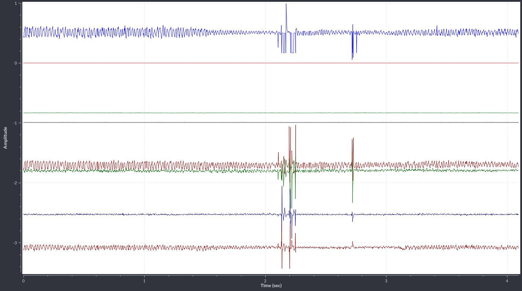
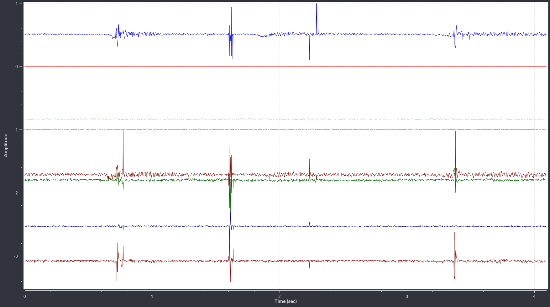
These were recorded with a Prototype 9.1 with two Electrode Module 3.1, one with 1x MCP6N11-100 at a gain of x501, and one with 4x INA128 with gains of x501 as well. I'm wearing it much like on the P8 demo video, except that there's two electrode modules side by side, not just one.
In the top center of the first picture (light blue signal), you can see that there is some clipping in the negative peaks of the wavelet, which is not great, but other than that, it does seem to show very similar signals. (They shouldn't be identical, of course, because each signal measures electrodes at different locations on the arm)
There's also a similar chip, the MCP6N16, which has a smaller footprint size and better performance, but has slightly higher cost and worse availability. It's more difficult to solder, too. But it's good to know that there's the option to switch to that one if we ever need to.
I'm quite happy with this result, and perhaps the next iteration of the electrode module will be designed for this chip rather than the INA128. :)
Next Steps & Resources
└2022-02-16, by RomanThe PsyLink Wiki now contains two new pages:
- Next Steps documents potential directions that he project could take in the future
- Resources points to external pages that are connected to PsyLink, similar projects, related news, papers, and educational material.
If you have suggestions for potential next steps or know about interesting links, please let me know, or add them to the wiki. :)
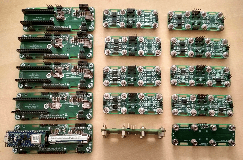
Mass production
└2022-02-15, by RomanMore and more people are asking me to send them a PsyLink prototype! I've written some Tutorials to help the users to get started, and I'm working diligently to assemble them all. Can't wait to see the ways in which they will be used. :)
Request your own pre-assembled PsyLink now too!
Unlike software, unfortunately, you can't just download a PsyLink and use it right away. It takes me about 1-1.5 hours per module to assemble these. I wish I could automate and outsource more of the assembly process, but I don't see a low hanging fruit worth exploring so far. Still, I'm happy about the progress, since I'm now ~5x faster than when I sent out the first Prototype 7.
Currently, the assembly process consists of:
- File off the rough break-off points on the PCB to avoid scratching the skin
- Solder on the SMD components
- Do optical quality tests, as well as tests with a multimeter on critical parts
- Since my pin sockets have 16 pins and the Arduino has 15 pins, I cut off one of the pins of the socket
- Cut the downward-facing pins of all through-hole components down to ~1.4mm so that they don't stick out of the PCB and possibly scratch the skin
- Solder on the Through-hole components (except battery clips)
- Plug in the battery clips, bend its pins inward so that they don't scratch the skin, (the end may break off but that's ok), and solder them on
- Clean off solder flux stains with Isopropyl Alcohol on the sides that face the skin
- Cover the bottom of the power module with insulating tape to avoid skin contact
- Screw on the electrodes / legs
- Wire up everything as described in the wiki
- Push the elastic band through the respective holes to connect the boards together
- Do a test run of the entire system
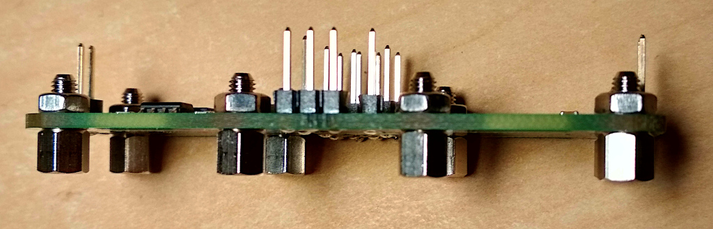
Outsourcing pick&place and soldering of the components would be helpful, but the through-hole components (pin headers/sockets, switch, battery clip) need special treatment: I have to trim the pins so that they don't stick out of the PCB and scratch the skin. I doubt that any pick&place contractor will do this for me. This close-up shot of a shows it well, that there are no sharp points under the pin headers, just round solder blobs:
But I could at least outsource the soldering of SMD components. Let's see if I can find something cheap.
If you have tips to accelerate the assembly process, please reach out to us.