PsyLink is experimental hardware for reading muscle signals and using them to e.g. control the computer, recognize gestures, play video games, or simulate a keyboard. PsyLink is open source, sEMG-based, neural-network-powered, and can be obtained here.
This blog details the steps of building it and shows recent developments. Subscribe to new posts with any RSS reader, and join the community on the Matrix chatroom.
- All posts on one page
-
2025-05-01: PsyLink Talk
-
2024-08-16: Mass Production #2
-
2024-08-01: Android: First Step
-
2024-07-25: Rev2 Firmware
-
2024-07-24: Prototype Fund
-
2023-08-25: Data Sheets
-
2023-05-31: Prototype 10
-
2023-03-22: Enhanced Signal by >1000%
-
2023-03-06: Sample Signals
-
2023-02-05: 2022 Retrospective
-
2022-02-24: Added Bills of Materials
-
2022-02-23: 3M Red Dot electrodes
-
2022-02-22: Microchip 6N11-100
-
2022-02-16: Next Steps & Resources
-
2022-02-15: Mass production
-
2022-01-19: Prototype 9 + Matrix Chatroom
-
2022-01-18: HackChat & Hackaday Article
-
2021-12-19: Prototype 8 Demo Video
-
2021-12-18: Prototype 8
-
2021-12-16: INA155 Instrumentation …
-
2021-12-15: Power Module 4
-
2021-11-30: Batch Update
-
2021-07-17: Neurofeedback: Training in …
-
2021-07-06: New Frontpage + Logo
-
2021-06-24: Cyber Wristband of Telepathy …
-
2021-06-21: Running on AAA battery
-
2021-06-16: Power Module 3
-
2021-06-10: Believe The Datasheet
-
2021-06-04: Back to the Roots
-
2021-05-31: Website is Ready
-
2021-05-29: Dedicated Website
-
2021-05-17: Gyroscope + Accelerometer
-
2021-05-14: Wireless Prototype
-
2021-05-09: Power Supply Module
-
2021-05-07: New Name
-
2021-05-06: Finished new UI
-
2021-05-04: Higher Bandwidth, new UI
-
2021-04-30: PCB Time
-
2021-04-29: Soldering the Processing Units
-
2021-04-28: Going Wireless
-
2021-04-24: First Amplifier Circuit
-
2021-04-19: Amplifiers
-
2021-04-15: Multiplexers
-
2021-04-14: Data Cleaning
-
2021-04-13: Cyber Gauntlet +1
-
2021-04-11: Adding some AI
-
2021-04-09: F-Zero
-
2021-04-08: Baby Steps
-
2021-04-03: The Idea
Prototype 9 + Matrix Chatroom
└2022-01-19, by RomanNews #1: PsyLink now has a Matrix chatroom: #psylink:matrix.org
News #2: PsyLink is now out, which is pretty much the same as Prototype 8, just with a few bugfixes and enhancements. Notably:
- The Power switch now actually fits on the power module
- The Battery clip doesn't intersect with a solder jumper anymore, which used to cause a short-circuit unless you'd cover it up with tape
- The built-in electrodes on the electrode modules now can be activated/deactivated via solder jumpers, which allows you to use external electrodes while wearing the PsyLink regularily, without the built-in electrodes interfering with the signal.
Obligatory Picture:
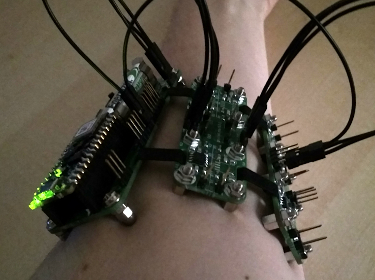
It's less colorful and has more boards than the photo of the P8, but that's just the type of wires, and an additional electrode module. You could make the P8 look the same way.
HackChat & Hackaday Article
└2022-01-18, by RomanSomeone at Hackaday kindly invited me ("hut") to host a Hack Chat about Electromyography and PsyLink on Wednesday, January 19, 8 PM GMT. There, I will answer all sorts of questions from the hackaday community.
Drop by too, and watch me struggle for an hour to pretend that I know what I'm talking about :)
Someone else at Hackaday also kindly wrote a whole article about PsyLink, which sparked nice discussions in the comments, got the P8 Demo Video over 5k views, and inspired several tinkerers to reach out to me about getting their own PsyLink :)
Prototype 8 Demo Video
└2021-12-19, by RomanThe demo video of Prototype 8 is out now:
Prototype 8
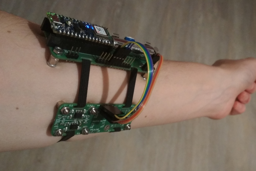
└2021-12-18, by RomanThe order of the PCB of has arrived, and so all the parts for Prototype 8 are finally here :) After some assembly (and crimping of some rainbow-colored connectors that look a little neater than those stray black wires from previous photos), this is the final picture:
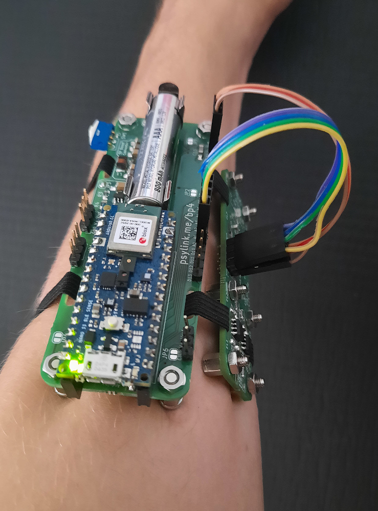
And another picture:
The Signal
A sample of the signal is this, using an INA128 with a gain of x228 and electrodes near the flexor digitorum superficialis:
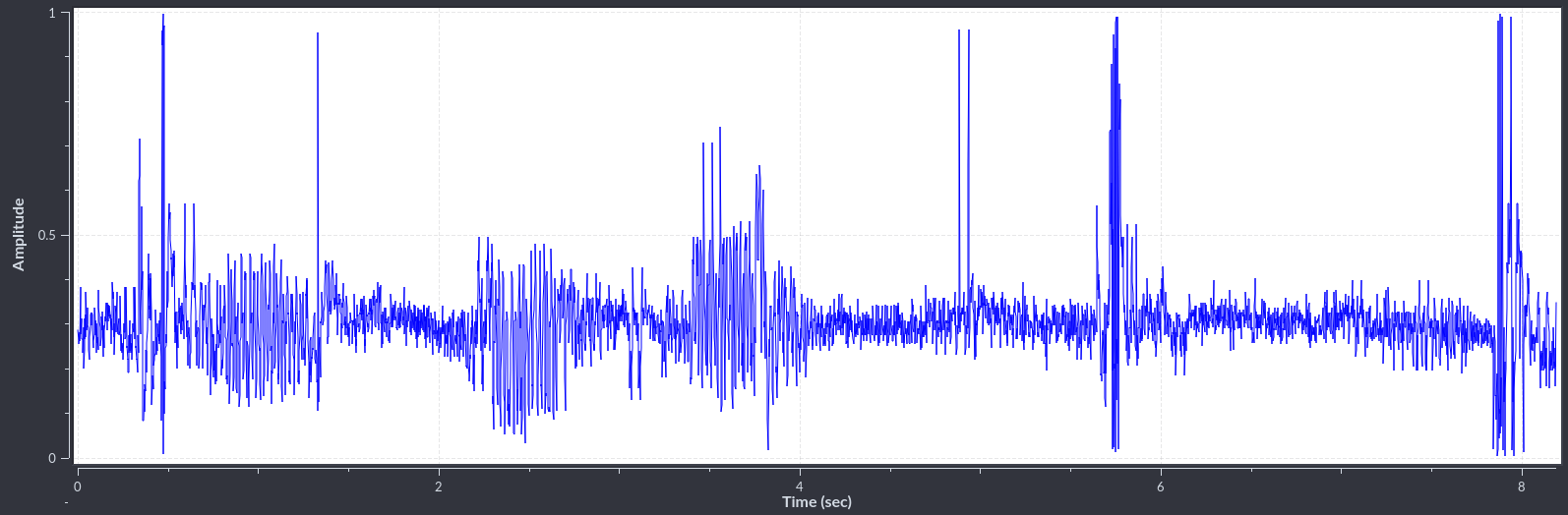
The baseline is the midly noisy line around a value of 0.3 and shows the state of rest.
The spikes and "spindles" (periods of higher amplitude) occured when I performed various movements, like extending the arm, snapping the fingers, or twisting the wrist.
Bugs in the BP4
The is not perfect though:
- The solder jumper J8, that activates the central Screw 5, overlaps with the battery clip, resulting in a short circuit with the battery's ground, unless I put some isolation tape over the jumper... Need to move the jumper further away.
- The power switch (SW1) is too close to the Screw 2, so the switch I wanted to use didn't actually fit, and I had to fall back to one that points off to the side, and looks a little awkward.
- I also wish that the analog pins were closer to the power pins, so that I can bundle up the wires, resulting in what would appear like one single connector, rather than two, per . Although this may lead to EM interference between the wires, reducing the quality of the signal, so maybe it's actually better this way.
INA155 Instrumentation Amplifier
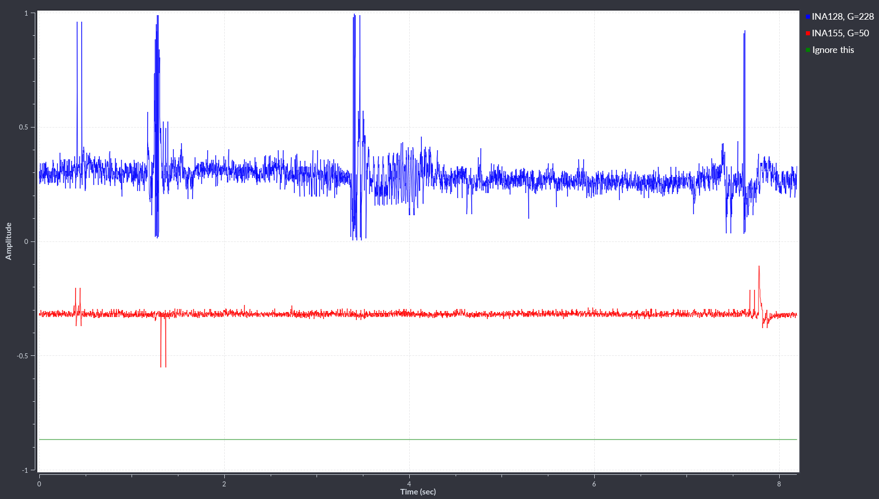
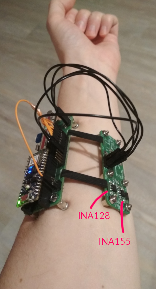
└2021-12-16, by RomanI tried replacing the INA128 chips on the with INA155 chips with a Gain of 50, and it works just fine :) The signal even looks a little bit cleaner than with the INA128, though I don't have good metrics to decide which one is better overall. They both have the same PCB footprint so I didn't even have to change the board design :)
This is good news. If I buy the INA155 chips in bulk (250+), they would cost ~1.75€ each (and I currently pay ~5.65€ per INA128), which would bring the material cost of the whole product down from ~60€ to ~30€ plus Arduino (~38€) plus shipment. Even if the INA155 is slightly worse, that's totally worth it.
At this price, it would even be affordable to use more than 8 signals (with additional analog multiplexing, since the Arduino only has 8 analog inputs) and wear more than two at the same time.
Another big plus is that INA155 chips can easily work with a supply voltage of 3.3V!! And I wouldn't need to boost the battery voltage all the way up to 5V anymore, which is probably not very power efficient.
CORRECTION
I did some more tests and concluded that with the electrodes that I'm currently using, the maximum gain of INA155 is not high enough, and I have to either find better electrodes, add extra amplifiers, or switch back to INA128 for the time being. For now, the relatively expensive INA128s will have to do.
But hey, the current electrodes are literally just... plain metal spacer screws, so there is DEFINITELY room for improvement.
Here are some pictures of electrode placement and resulting signals, where you can see that the INA128 (blue line) shows considerably more features: