PsyLink is experimental hardware for reading muscle signals and using them to e.g. control the computer, recognize gestures, play video games, or simulate a keyboard. PsyLink is open source, sEMG-based, neural-network-powered, and can be obtained here.
This blog details the steps of building it and shows recent developments. Subscribe to new posts with any RSS reader, and join the community on the Matrix chatroom.
- All posts on one page
-
2025-05-01: PsyLink Talk
-
2024-08-16: Mass Production #2
-
2024-08-01: Android: First Step
-
2024-07-25: Rev2 Firmware
-
2024-07-24: Prototype Fund
-
2023-08-25: Data Sheets
-
2023-05-31: Prototype 10
-
2023-03-22: Enhanced Signal by >1000%
-
2023-03-06: Sample Signals
-
2023-02-05: 2022 Retrospective
-
2022-02-24: Added Bills of Materials
-
2022-02-23: 3M Red Dot electrodes
-
2022-02-22: Microchip 6N11-100
-
2022-02-16: Next Steps & Resources
-
2022-02-15: Mass production
-
2022-01-19: Prototype 9 + Matrix Chatroom
-
2022-01-18: HackChat & Hackaday Article
-
2021-12-19: Prototype 8 Demo Video
-
2021-12-18: Prototype 8
-
2021-12-16: INA155 Instrumentation …
-
2021-12-15: Power Module 4
-
2021-11-30: Batch Update
-
2021-07-17: Neurofeedback: Training in …
-
2021-07-06: New Frontpage + Logo
-
2021-06-24: Cyber Wristband of Telepathy …
-
2021-06-21: Running on AAA battery
-
2021-06-16: Power Module 3
-
2021-06-10: Believe The Datasheet
-
2021-06-04: Back to the Roots
-
2021-05-31: Website is Ready
-
2021-05-29: Dedicated Website
-
2021-05-17: Gyroscope + Accelerometer
-
2021-05-14: Wireless Prototype
-
2021-05-09: Power Supply Module
-
2021-05-07: New Name
-
2021-05-06: Finished new UI
-
2021-05-04: Higher Bandwidth, new UI
-
2021-04-30: PCB Time
-
2021-04-29: Soldering the Processing Units
-
2021-04-28: Going Wireless
-
2021-04-24: First Amplifier Circuit
-
2021-04-19: Amplifiers
-
2021-04-15: Multiplexers
-
2021-04-14: Data Cleaning
-
2021-04-13: Cyber Gauntlet +1
-
2021-04-11: Adding some AI
-
2021-04-09: F-Zero
-
2021-04-08: Baby Steps
-
2021-04-03: The Idea
Dedicated Website
└2021-05-29, by RomanThe PsyLink project now has it's own website: psylink.me, and this is the place where I will continue the development log, as soon as I finish the basic structure of the website.
Gyroscope + Accelerometer
└2021-05-17, by RomanI fixed up the PsyLink UI. It was so broken after the rewrite to Bluetooth Low Energy, I'm once again stunned that I got ANY useful results before. But now it receives the transmissions from the Arduino properly.
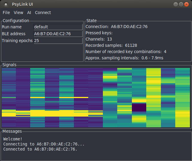
I also added 6 more signal channels: The x/y/z-axes from the Gyroscope and from the Accelerometer that are built in to the Arduino Nano 33 BLE Sense.
All put together finally allowed me to singlehandedly drive through the finish line of my favorite racing game F-Zero! \o/
- For training the AI, I recorded 60k samples over 2 minutes (500Hz)
- Trained for 5 epochs, which took 1 minute without GPU acceleration
- 4 training labels ("left", "right", "accelerate", "nothing")
- Final training and validation loss: 0.04, accuracy: 98%
- 6 layer neural network with 2 convolutional layers
- Music by Mitch Murder
Wireless Prototype
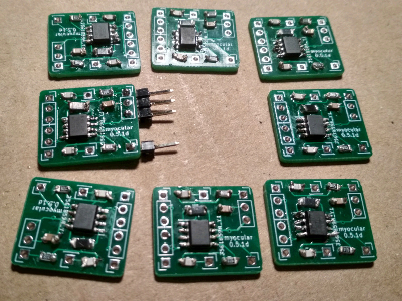
└2021-05-14, by RomanHell yeah! The PCBs arrived:
Soldering & Sewing
I never soldered such tiny SMD parts before, and didn't have proper tools, way too thick soldering tin and solder iron tip. I was also too impatient to order some, so after hours of torture, I produced this batch:
The new prototype was to be a forearm sleeve of modal fabric once again, with snap buttons for electrodes which will also hold the signal processing PCBs in place.
But how to attach the Arduino and the power supply module to the sleeve? I thought, "why not Velcro?" (hook-and-loop fastener) and started sewing it to the circuit boards:
(Yes, doing it felt as weird as it looks)
So I sewed the sleeve, assembled one electrode pair along with its processing PCB, and wired everything together. Here's me being overly excited about the first wireless test run:
Electrode Placement
Then there was the question of where to put the electrodes. Using an improvised muscle map along with two flexible electrodes on individual straps, I could find spots whose electrical activity correlated with turning the arm, twisting the wrist, or pressing individual fingers onto the table:
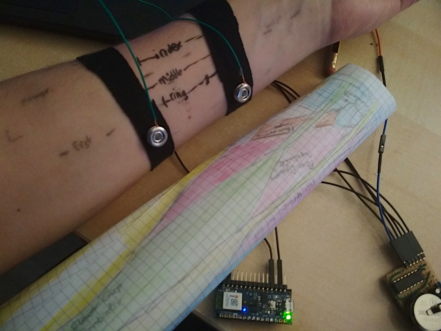
Flexor Digitorum Superficialis was particularly interesting; I found 3 areas over that muscle which map to the index, middle and ring finger each. For turning the arm and wrist, the muscles with "Carpi" in their name (e.g. Extensor carpi ulnaris) worked pretty good.) A huge disappointment was Extensor Digitorum, which is supposed to be active when fingers move up, but I could not find such correlation. Then again, I use snap buttons for electrodes, so I'm not that surprised.
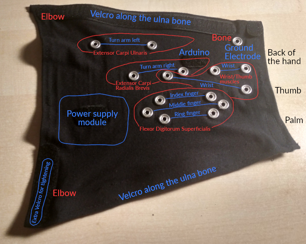
The final layout of the electrodes:
This piece is fully separable from the electronics and therefore machine washable.
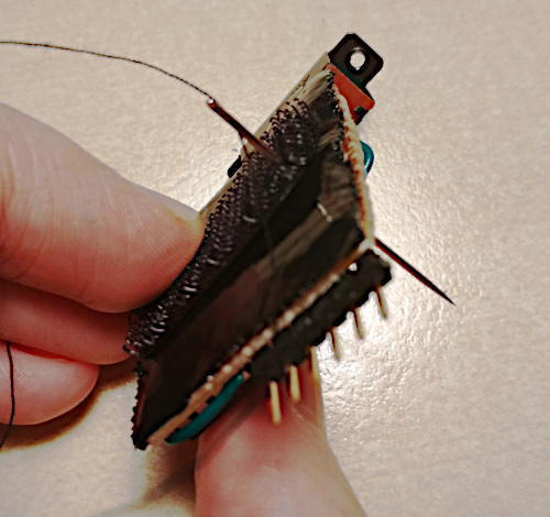
Here are additional pictures of the inner side, the separated electronics, as well as everything combined. This nicely shows the tree topology of the green signal processing modules that pass through the power supply among each other to reduce the volume of wiring.
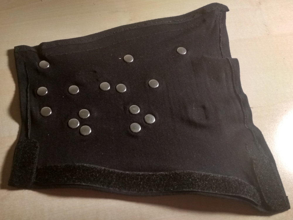
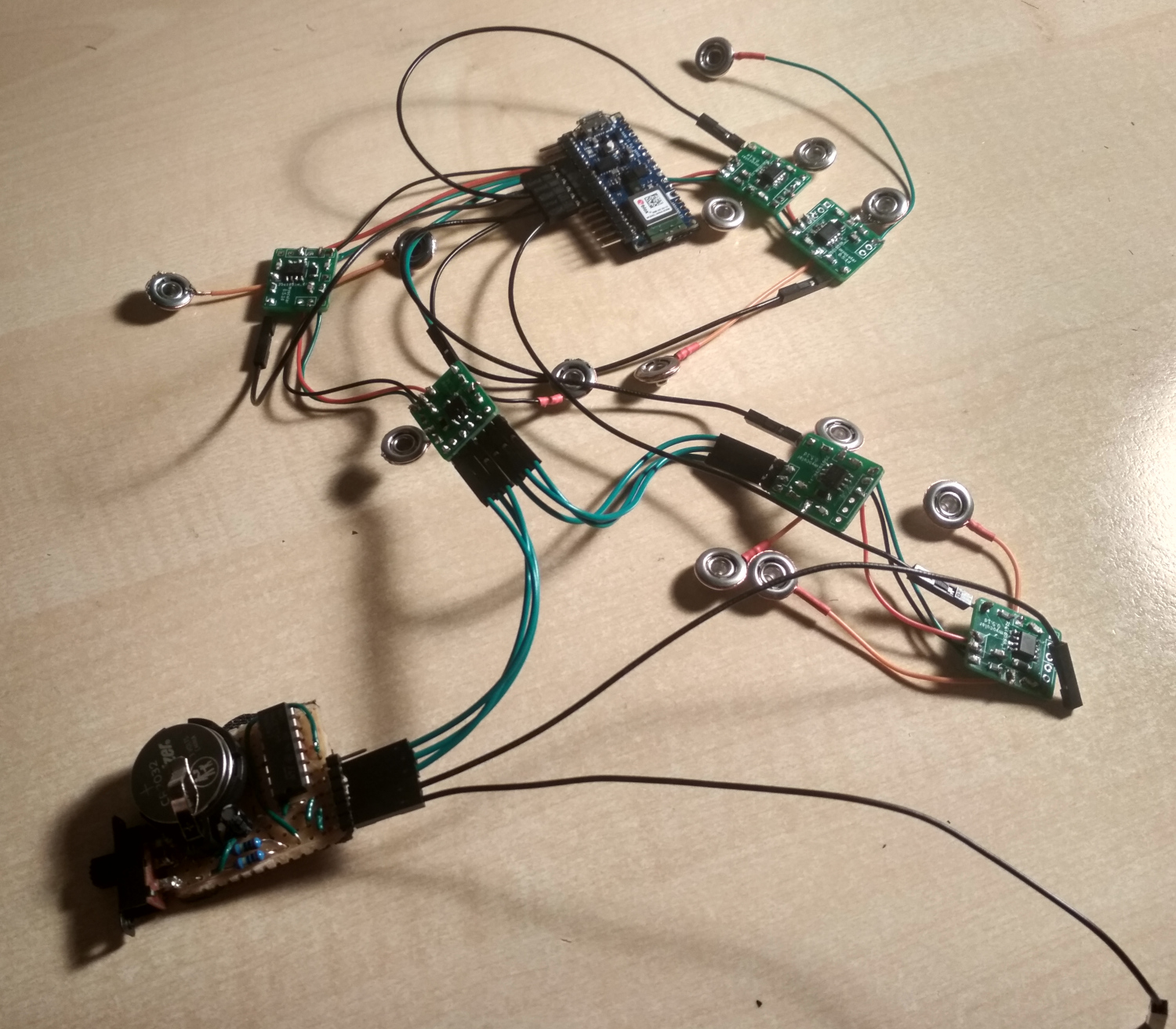
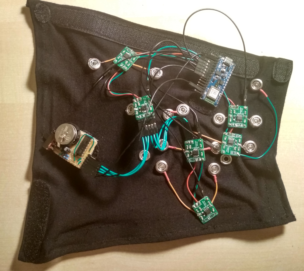
I could have had 8 electrode pairs, but only added electrodes for 7. On these pictures, the electrode pair for the middle finger is also missing the circuitry. That's mostly a testament to my laziness.
Actually I regret where I placed the Arduino, since there would be some great spots for electrodes, but I noticed that too late. Will try to remove the Velcro and maybe add an 8th electrode pair there.
The final cyb3rware:
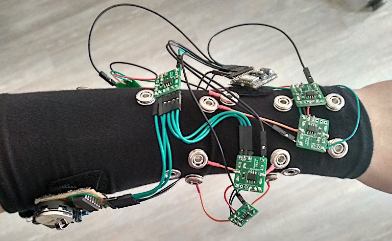
While the signal was quite strong with the test straps, I found that the amplitude of the signal went way down once I had everything attached to the sleeve. Maybe there was some kind of interference from the Arduino or the power supply being closer to my skin, or maybe the modal fabric messes with the signal somehow. I hope I can compensate for this by increasing the signal amplification multiplier, but I leave that for later.
This issue occurred with a single electrode pair already, but was aggravated when attaching more of them. It might help if I add some flux capacitors to the power supplies to prevent cross-interference.
Test Drive
I drove F-Zero with Prototype #2 before, but back then I cheated a little bit. It only recognized 2 keys, left and right, and I accelerated with the keyboard using my other hand.
This time I hoped I could do better, and trained the AI to recognize 3 different keys (left, right, accelerate) from my muscle signals. It even kinda worked!
This was after recording ~2000 muscle signal samples over 1-2 minutes and training a convolutional neural network for 25-50 epochs (<1 minute) on the data using the PsyLink UI. I used 4 electrode pairs, all of which are on the dorsal side of the forearm.
Analysis
In the racing game, I didn't make it to the finish line yet, and it does look pretty clumsy, but I blame it on the software still having some obvious flaws. It doesn't even account for packet loss or packet duplication when handling the Bluetooth packets yet. Hope it will go better once I fixed them. Also, the test drive was with only 4 electrode pairs.
The raw values as visualized with the GNURadio flowgraph while randomly moving my forearm/wrist/hand show that the correlations between the signals are low enough to be theoretically useful:

If you enlarge this image, you'll see that especially the black line is considerably different, which I suppose is because it's the only electrode pair that spans across several muscles. And that makes me wonder: Am I doing too much pre-processing in hardware before I feed the data into the AI? Sure, the differential amplification of this new prototype enhances small signals that the previous prototypes might have not detected, but a lot of information is lost too, like the voltage differences between electrodes from different electrode pairs.
Maybe I can compensate for this by simply adding some more electrode pairs that span muscles. I'm also thinking of switching to a design with 32-64 randomly placed electrodes -> buffer amplifiers -> multiplexers -> analog to digital converters of the Arduino. That way, the neural network can decide for itself which voltage differences it wants to look at.
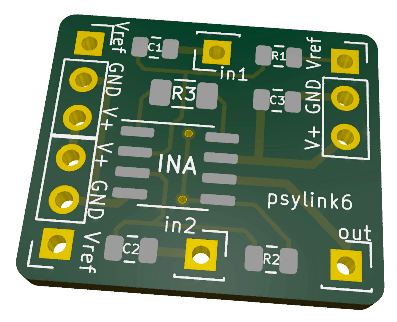
New PCB layout
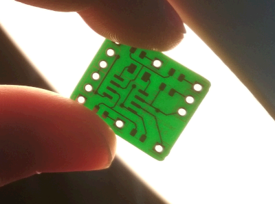
While soldering the PCB, I found some flaws and made these changes to the previous PCB:
- Added silkscreen labels to the connectors and components. I was sure I wouldn't mix up anything since there aren't many connectors, they're nicely symmetrical, and I'm the designer after all. But nope. I still mixed them up.
- Removed unnecessary vias. (I was actually not sure whether the pin holes will really conduct between the front and the back side of the board, so I added vias as a safety measure.)
- The label now shows the new name "psylink" instead of "myocular"
- A friend also gave me the tip to increase the thickness of power supply wires
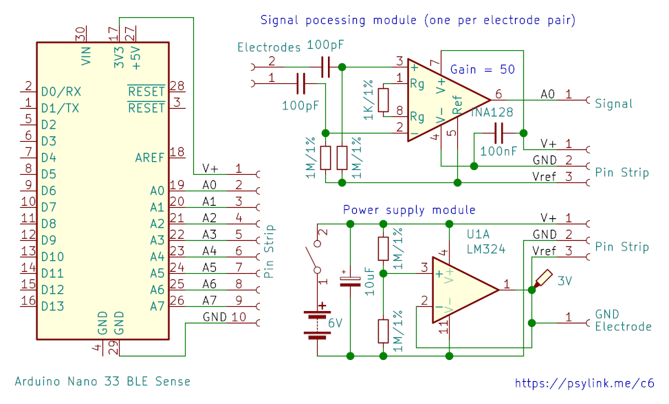
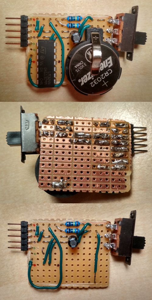
Power Supply Module
└2021-05-09, by RomanI made an updated schematic (circuit 6) that shows more clearly how the modules are connected. Also corrected an error with the feedback of the voltage follower, and changed values of some resistors/capacitors:
I also constructed the power supply module:

but for some reason it didn't work. All the parts seemed to have been connected the right way, I couldn't find a short circuit, but the output voltage was ~0.5V instead of ~5V, and the reference voltage was just 0. I blame a possibly broken opamp.
Well, I didn't like the design and length of the circuit board anyway, so it didn't hurt trashing the thing and building this beauty instead:
I'll use female-to-female jumper wires to connect V+ and GND to the arduino, and 3 more wires to bootstrap the power supply of the mesh network of the signal processing modules.
Notes:
- Yep, that's 2 coin cells in there
- Outputs: Black=Ground, Red=V+, Green=V+/2 (reference signal)
- There's an optional second green pin for the ground electrode
- If you're wondering why I'm using a big ass quad opamp when I just need a single output: I don't have a smaller one atm.
- I totally need to move this to a SMD PCB in the long run, this is still too bulky, but will do for now. It's about the dimensions of a 9V battery.
I wonder if some 深圳人 will read this, shake their head, and view me as a primate struggling to make fire with sticks. That's what it felt like to construct this thing anyway. Nevertheless, I'm one step closer to the next prototype :)
New Name
└2021-05-07, by RomanAfter some brainstorming, I changed the working title of this project from Myocular to ✨PsyLink✨. The close second favorite was FreeMayo (thanks to Vifon for the suggestion). Free as in free speech/software/hardware, and mayo as a play on myo (ancient greek for "muscle"). But somehow I liked PsyLink more. It's inspired by the Psionic Abilities from the 1999's game System Shock 2.
FYI, this is the list of words that I considered, although unfortunately many of the coolest combinations were taken:
- axon
- coil
- cortex
- cyber
- free
- gauntlet
- glove
- link
- loop
- magic
- mana
- mayo
- myo
- open
- pipe
- plug
- psi
- psionic
- psy
- psyber
- scan
- surge
- tron
- ware
- wave
- wear