PsyLink is experimental hardware for reading muscle signals and using them to e.g. control the computer, recognize gestures, play video games, or simulate a keyboard. PsyLink is open source, sEMG-based, neural-network-powered, and can be obtained here.
This blog details the steps of building it and shows recent developments. Subscribe to new posts with any RSS reader, and join the community on the Matrix chatroom.
- All posts on one page
-
2025-05-01: PsyLink Talk
-
2024-08-16: Mass Production #2
-
2024-08-01: Android: First Step
-
2024-07-25: Rev2 Firmware
-
2024-07-24: Prototype Fund
-
2023-08-25: Data Sheets
-
2023-05-31: Prototype 10
-
2023-03-22: Enhanced Signal by >1000%
-
2023-03-06: Sample Signals
-
2023-02-05: 2022 Retrospective
-
2022-02-24: Added Bills of Materials
-
2022-02-23: 3M Red Dot electrodes
-
2022-02-22: Microchip 6N11-100
-
2022-02-16: Next Steps & Resources
-
2022-02-15: Mass production
-
2022-01-19: Prototype 9 + Matrix Chatroom
-
2022-01-18: HackChat & Hackaday Article
-
2021-12-19: Prototype 8 Demo Video
-
2021-12-18: Prototype 8
-
2021-12-16: INA155 Instrumentation …
-
2021-12-15: Power Module 4
-
2021-11-30: Batch Update
-
2021-07-17: Neurofeedback: Training in …
-
2021-07-06: New Frontpage + Logo
-
2021-06-24: Cyber Wristband of Telepathy …
-
2021-06-21: Running on AAA battery
-
2021-06-16: Power Module 3
-
2021-06-10: Believe The Datasheet
-
2021-06-04: Back to the Roots
-
2021-05-31: Website is Ready
-
2021-05-29: Dedicated Website
-
2021-05-17: Gyroscope + Accelerometer
-
2021-05-14: Wireless Prototype
-
2021-05-09: Power Supply Module
-
2021-05-07: New Name
-
2021-05-06: Finished new UI
-
2021-05-04: Higher Bandwidth, new UI
-
2021-04-30: PCB Time
-
2021-04-29: Soldering the Processing Units
-
2021-04-28: Going Wireless
-
2021-04-24: First Amplifier Circuit
-
2021-04-19: Amplifiers
-
2021-04-15: Multiplexers
-
2021-04-14: Data Cleaning
-
2021-04-13: Cyber Gauntlet +1
-
2021-04-11: Adding some AI
-
2021-04-09: F-Zero
-
2021-04-08: Baby Steps
-
2021-04-03: The Idea
Finished new UI
└2021-05-06, by RomanThe new user interface now supports all previous features!
- Capturing muscle signals
- Capturing the keys that the user is pressing
- Training a neural network to predict key presses from given signals
- Auto-pressing keys based on incoming signals using said neural network to predict which keys the user wants to press
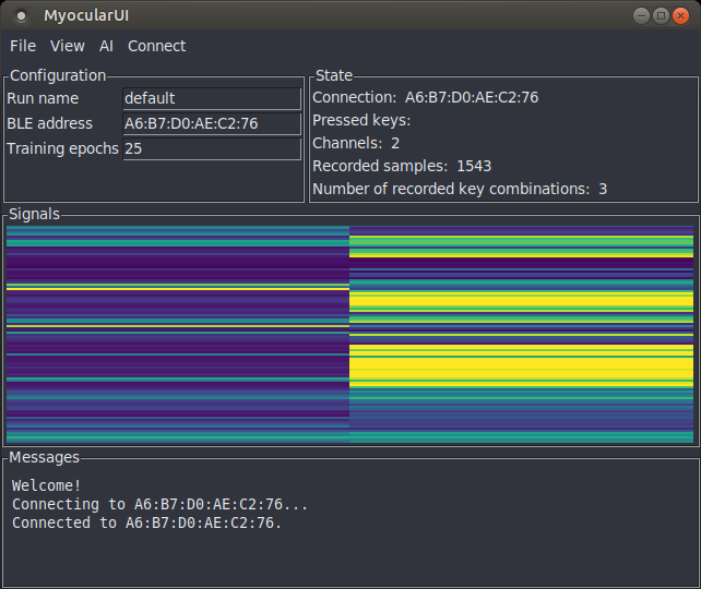
It's sooo much more pleasant to have a direct view on the state of the application and an instant visualization of the signals. The previous version was literally just a blank window, with a single menu called "File" that contained all the actions. :D I never even bothered to upload a screenshot, but here's one for documentation purposes:
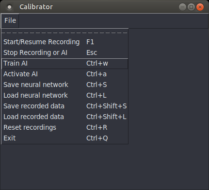
Also, this time I used clean & efficient data structures to make the code easier to work with, a more reliable key capturing library (pynput), and threads to prevent one activity from blocking the others. The signals obviously go via Bluetooth instead of a wired serial connection.
I'm also thinking of changing the name for the project, since people are reading it as "my ocular" rather than recognizing the neologism made of "myo" (for "muscle") and "ocular" (from "eye"). But all the good names are taken, of course. -_-
Higher Bandwidth, new UI
└2021-05-04, by RomanHah, I managed to raise the Bluetooth bandwidth from ~1kB/s to 6-7kB/s with this one magic line:
BLE.setConnectionInterval(8, 8);
It raises the power consumption by 4% (3.5mW), but that's totally worth it. I can now get all 8 channels in 8-bit resolution at 500Hz across the aehter. Eventually I should aim for 10-bit at 1kHz, but I think that can wait.

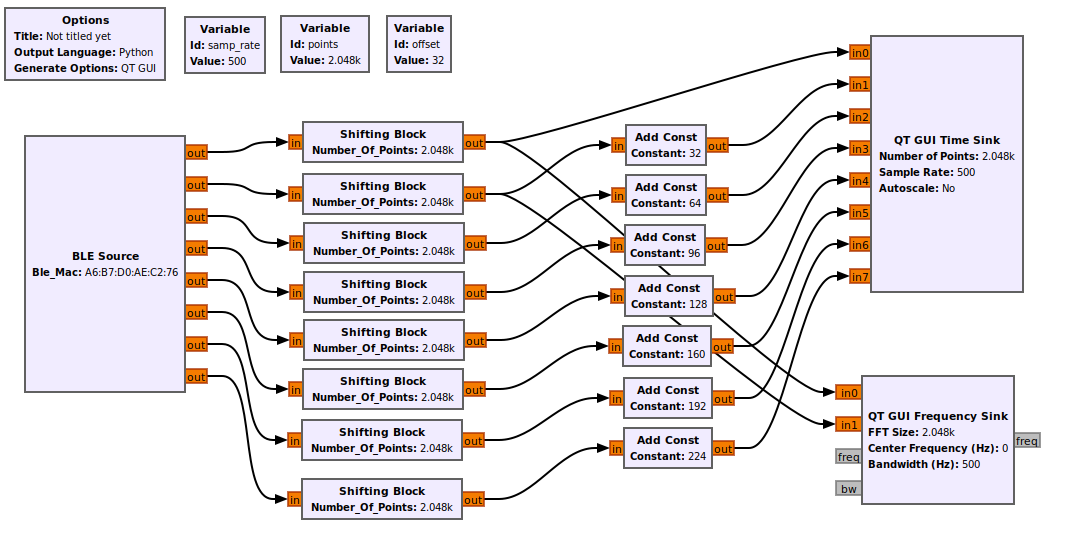
This is the GNURadio flowgraph and the resulting output. (I only have hardware for 2 electrode pairs, so even-numbered and odd-numbered signals are wired to the same input. Still waiting for the PCBs.)
Power ratings:
- No Bluetooth connection: 86.9mW (16.9mA x 5.14V)
- Transmitting at 1-2kB/s: 88.9mW (17.3mA x 5.14V)
- Transmitting at 6-7kB/s: 92.5mW (18.0mA x 5.14V)
Surprisingly to me, the LEDs were draining a good chunk of the power, and I saved 16mW by removing the external power LED (see previous photo) and by PWM-dimming the blue LED that indicated Bluetooth connections. It gives me approximately 15 hours run time with 2x CR2032 coin cells.
Also I'm in the process of rewriting the UI:
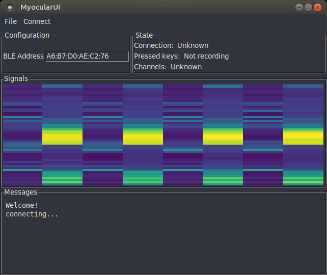
The colorful column graph is a live visualization of the signal. The columns correspond to electrode pairs, while the rows are time frames. The top row shows the amplitude of the signal at the current time, and the rows flow downward, allowing you to view changes back in time, as well as correlations between signals.
You'll also be able to change settings on the fly, view the status of e.g. key recordings or machine learning processes, and more. All of this is in a modular library that will also be usable from e.g. GNURadio.
I was thinking of changing the graphical user interface toolkit from Tkinter to a more modern one, because Tkinter looks a little shabby, and it has problems determining which keys are currently pressed, but I decided against it, because I made the experience of being unable to run my own software several years after writing it because the exact version of the GUI toolkit, along with all dependencies, was too annoying to set up. Tkinter has been around for decades and will probably stay, so I'll stick with it for now. Also, I can easily solve the key pressing issue with an external key tracking library like pynput.
Can't wait to try out the new UI with 8 individual electrode pairs, once the PCBs arrive! (assuming they work :'D)
PCB Time
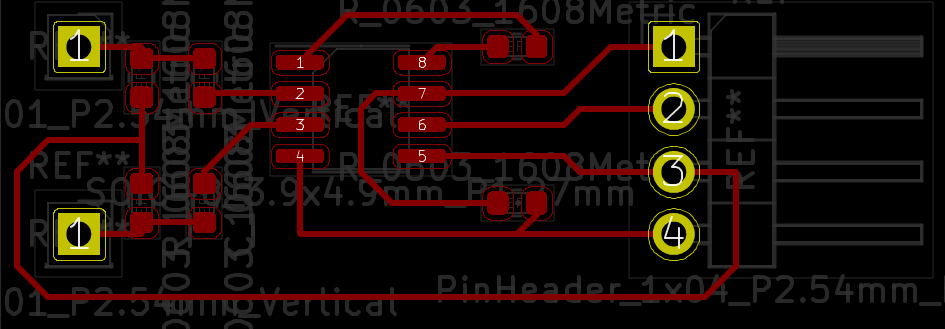
└2021-04-30, by RomanToday I made a new version of the PCB that processes the signals from one electrode pair:
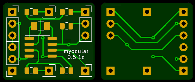
Actually, several versions. This is the 4th iteration, and let's not even look at the previous ones because they were just plain wrong. I stared at this design for a long time though and couldn't find another problem, so I went ahead and ordered 30 pieces of it. Can't wait to find out in what way I messed up :'D And hey, maybe it'll actally work.
Main features:
- Dimensions: 20x17x1.6mm, rounded corners
- Tiny enough to fit between 2 electrodes!
- 2 connectors for electrodes, at the middle top & bottom
- 1 connector for the output at the bottom right corner (on the front side. The back side is mirrored)
- 3 power line connector ports on the other corners, with 3 pins each:
- The signal reference voltage
- Ground
- +6V from the battery
- 3 capacitors, 3 resistors, 1 integrated circuit
To avoid having a kilogram of cables on the device, this board supports wiring in a mesh network topology, where the boards share the power lines amongst each other using the redundant power line connector ports. One board can power two other boards, which in turn can power 4, and so on.
The bypass capacitor between ground and V+ will hopefully keep the voltage stable, though I'm a bit worried about the reference signal. If necessary, I can "abuse" the reference signal pin of the power line connector ports to add extra ground electrodes. I considered adding an extra opamp on every board to generate a fresh reference voltage but that would make the circuit too big for my taste.
Soldering the Processing Units
└2021-04-29, by RomanThe plan was to split the circuit into:
- 1 central part including the Arduino, power supply and the OpAmp that generates the signal ground, and
- 8 distributed signal processing units, embedded in hot glue for stability and electrical insulation, consisting of an instrumentation amplifier and related components, close to the electrodes to avoid signal degradation.
Here's my try to solder one of those units:

This took me over an hour, during which I began questioning various life choices, started doubting this whole project, poured myself a Manhattan cocktail, wondered how long it would take to complete all eight of these, whether it will even be robust enough to withstand regular usage of the device (NO, IT WON'T), and how I'm going to fix the inevitable broken solder joints when the entire thing is in fucking hot glue...
I gave up, and now my plan is to get PCBs for this instead. I have little experience with this, so I've been putting it off, but how hard can it be?
First draft:
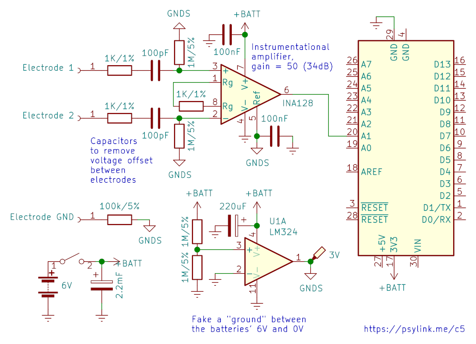
Updated schematic:
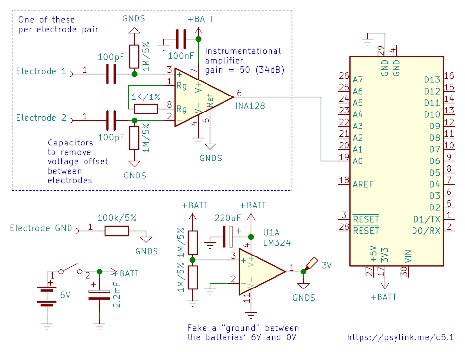
I removed the decouplying capacitor between ground and GNDS (signal ground) by the REF pin of the INA128 because mysteriously it made the signal worse, not better. Also removed the 1K resistors between electrodes 1+2 and the respective capacitors, because they served no apparent purpose.
Also, I was frustrated that GNURadio doesn't allow you to get a "rolling" view of a signal. The plot widget buffers as many samples as it can show, and only when the buffer is full, it updates the graph, clears the buffer and waits again. I wanted instant updates as soon as new samples are in, and as a quick&dirty workaround I wrote a GNURadio shift block which keeps filling up the buffer of the plotting widgets.
I'll finish with a nice picture of a finger snap, as recorded with one electrode pair on my dorsal wrist. Click to enlarge and view the frequency domain as well. (Just one electrode pair because that's all I can squeeze out of the poor bluetooth low energy bandwidth so far)

Going Wireless
└2021-04-28, by RomanI've been battling with reducing the power line noise for too long, so I thought screw it, let's go off the power line entirely. I put the circuit on two 3V CR2032 coin cells and wrote some code to transmit the signals via BLE (Bluetooth Low Energy) using the ArduinoBLE library.
Since I can not plot the signals via the Arduino IDE plotter anymore, I switched to GNURadio and wrote a plugin that establishes the BLE connection and acts as a signal source in the GNURadio companion software
My new "electrodes" also arrived: Simple prong snap buttons. They don't have sharp edges like the pyramidal studs I used before, and allow me to easily remove the wires from the electrodes and plug them in somewhere else as needed.

I also employed INA128 instrumentation amplifiers, drastically reducing the complexity of the circuit. It's a tiny SMD chip, which I plan to embed in hot glue, along with the 3-4 capacitors and 3-5 resistors required for processing/de-noising, and place 8 of these processing units across the glove/wristband, connected to two electrodes each.
Now I'm battling the problem that I can only get about 1kB/s across the ether. How am I supposed to put 12kB/s worth of signal in there? (8 channels, 1k samples/s, 12 bit per sample) Let's see if I can find some nice compression method, but I fear that it's going to be lossy. :-/