Power Module 4
Prototype 8 needs a matching power module. I can't continue to awkwardly stuff the rubber band between the velcro and the PCB of Power Module 3 like this:

We need a PCB with proper rubber band holes and screw mounting points, so it can be worn along the radius bone with about 2x Electrode Module 3 beside it.
Unfortunately the large dimensions of the Arduino and the battery make it a little difficult. There's several options to do this, but none of them are perfect:
- Place Arduino and battery beside each other like in Power Module 3
and either...
- make the board ~15mm longer to fit the holes.
- Downside: The rubber band holes would be wider apart than on the Electrode Module 3
- make the board ~12mm wider to fit the holes.
- Downside: It would be too wide to comfortably fit on the radius bone
- Downside of both options: it might feel unbalanced when worn on the side of the arm, because the heavy battery moves the center of mass off to the side
- make the board ~15mm longer to fit the holes.
- Place Arduino and battery on top of each other, with pin sockets for the arduino that are taller than the battery, then make the board the size of Electrode Module 3 to fit the holes
- Downside: It might be hard to acquire pin sockets that tall
- Downside: Little space left for the holes and the remaining components, but might work
- Place Arduino and battery in a line next to each other and make the board 20mm longer and 8mm wider than Electrode Module 3 to fit the holes.
- Downside: The rubber bands are relatively close to the center, reducing the force with which the far ends of the board are pressed onto the skin
- Downside: The large dimensions might make it too bulky
- Remove the Arduino and solder the NINA-B306 bluetooth module of the Arduino onto the board directly, along with all the peripherals I need
- Downside: Unnecessary complexity
- Downside: More difficult soldering
- Instead of adding any holes, just stack the board on top of a Electrode Module 3 and use its screws and rubber band holes for physical support. (Thanks to PerlinWarp for that idea!)
- Downside: Would require a redesign of Electrode Module 3
- Downside: The height of the prototype might make it feel unbalanced
- Downside: The board would have be either wider or longer than the Electrode Module 3 due to the dimensions of the Arduino and battery. As a result, it would stick out to the sides, unless I enlarge the electrode board as well.
In the end I chose option 3 for simplicity reasons, and because the downsides seemed the most acceptable. This also gives me a lot of space on the PCB which is currently not needed, but may be used for analog multiplexing later on, to allow supporting more than 8 electrodes.
I am quite tempted by option 2 though, it would make for a really compact board. Maybe I give it a try later (if I ever find a source for 1x15 pin sockets that are 14mm+ tall and 2.54mm spaced apart.)
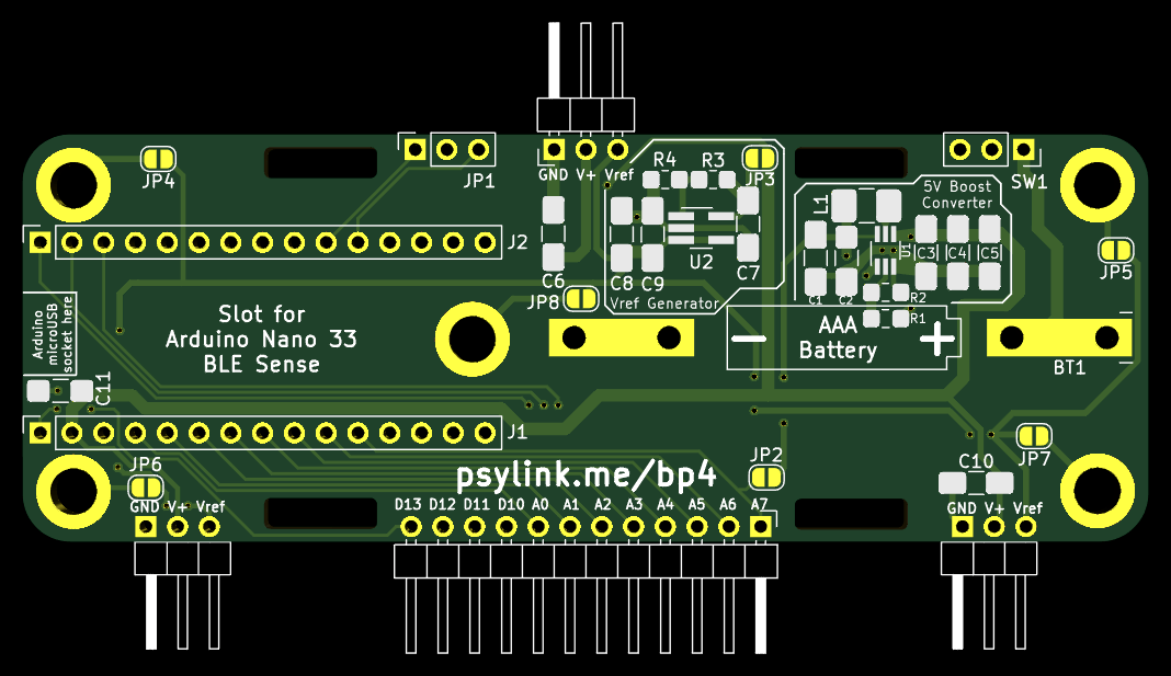
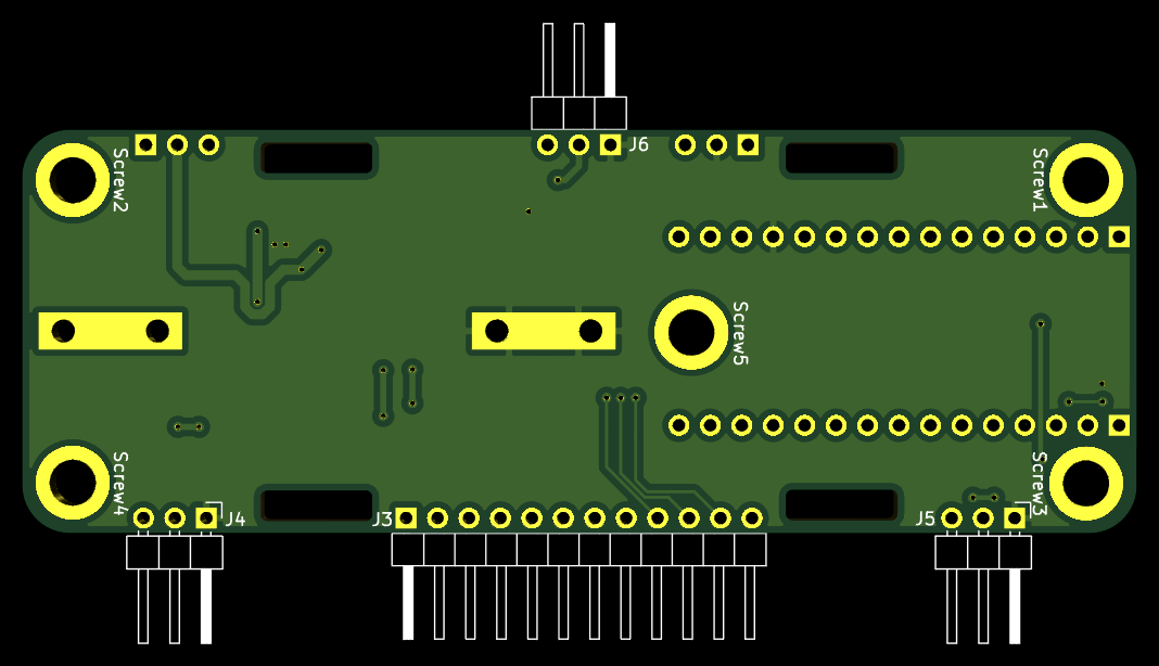
Here is the resulting board. As you see, I also added a screw mounting hole in the center, which should point right at the bone, which perhaps makes for a great ground electrode. Any of the screws can be used as ground electrodes though, simply by closing their respective solder jumper. I will try out various combinations to see which one is best.
The matching circuit:
I ordered the production of this board already, and I'm excited to see if it will work out like I imagine. :)
Fun story on the side: I ordered the boards on Aisler, and they let you change the PCB design for free until it hits production. This time, I had a couple of hours left, which I used to make a couple of adjustments here and there, until I was happy and went to sleep. After 3 hours I woke up, with racing thoughts, and I couldn't really fall asleep again (which happens very rarely). After laying awake for 2 hours, it occurred to me that I should run the automatic PCB layout check of KiCad once again to test my board for obvious mistakes. Of course I had run the check before submitting my order, and several times after doing my various modifications. But as it turned out, I had indeed forgotten to run it on the final version, and there were multiple errors too! Several unconnected nodes and some copper tracks that were too close to each other. Luckily I caught this just a couple minutes before my time for free modification ran out, and fixed it just in time. Thanks insomnia.
- Newer post: INA155 Instrumentation Amplifier
- Older post: Batch Update
- All posts on a single page
- Date: 2021-12-15
- Author: Roman


